RJ45 PUC wiring diagram

Home Forums General Discussion & Questions RJ45 PUC wiring diagram

Viewing 5 posts - 1 through 5 (of 5 total)
  • Author
    Posts
  • #10478
    petermc
      • Topics Started 2
      • Total Posts 13

      Hi,

      Would anybody have the wiring diagram for a RJ45 PUC cable?

      I’m having trouble sourcing a cable (seems to be a shortage) and was wondering if an existing cable with a 3.5mm pin could be repurposed with a RJ45 connector.

      Thanks

      Peter

      #25395
      Guy
      BRONZE Member
        • Warwickshire, UK
        • Topics Started 16
        • Total Posts 1,044

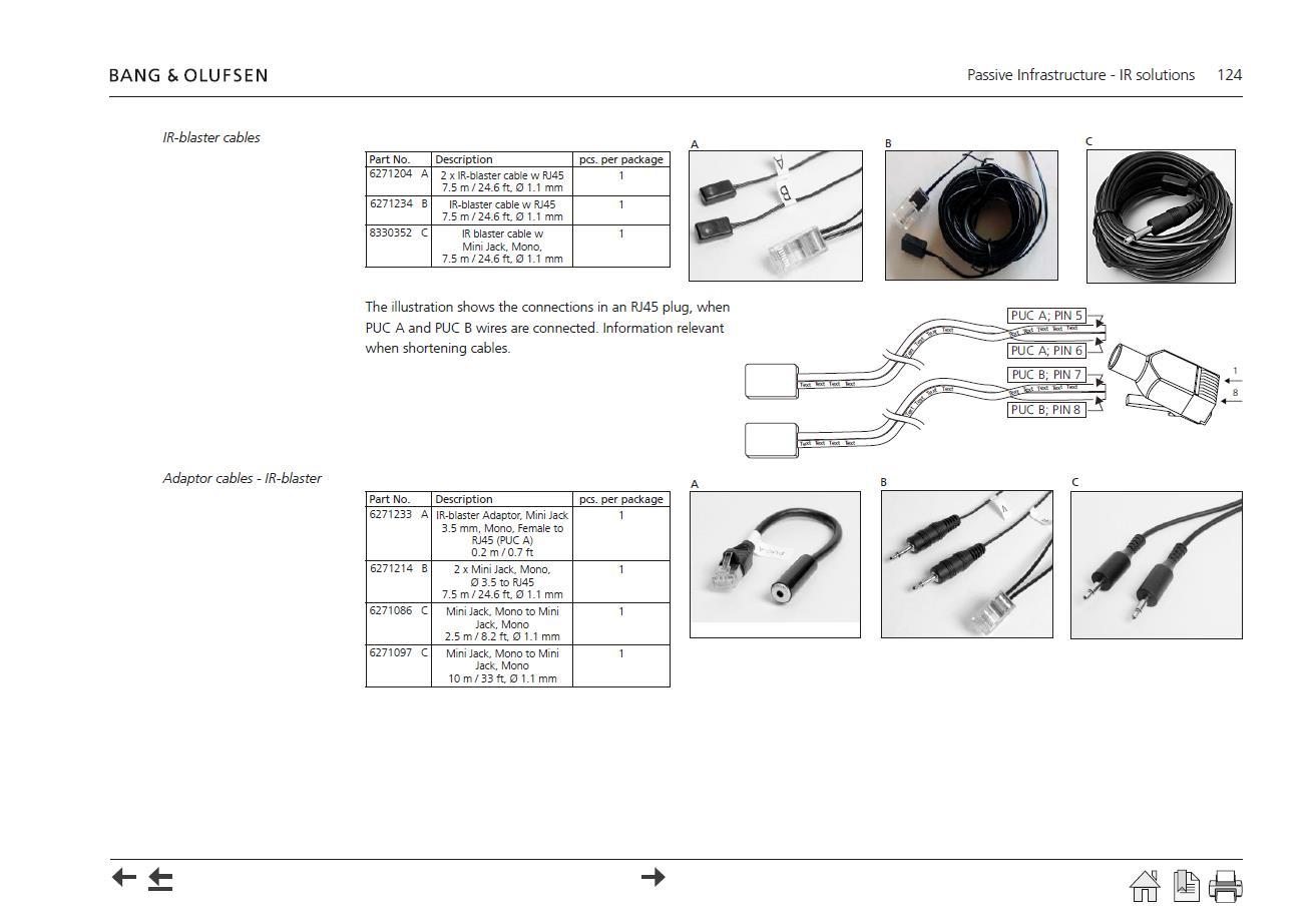
        Here’s the page from the Beolink Handbook v1.9.  It shows the adaptors also, but doesn’t actually map the connections across to confirm polarity (click to enlarge):

        puc

        #25391
        Guy
        BRONZE Member
          • Warwickshire, UK
          • Topics Started 16
          • Total Posts 1,044

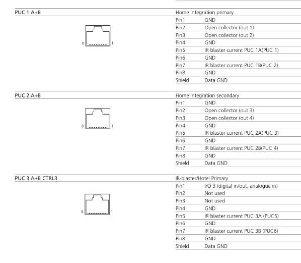
          Further to this – I checked against the BV10 and BV11 service manuals.  For the IR PUC with 3.5mm plug the tip is the IR signal.  For the RJ45 version, pins 5 and 7 are the IR signal (pins 6 and 8 being ground) – here’s the page in the BV11 manual:

          BV11 service manual page 88 (viewed on iPhone) - puc


          #25332
          petermc
            • Topics Started 2
            • Total Posts 13

            Thanks Guy for the info.

            I attempted to use an existing IR lead and convert to RJ45. That didn’t go well.

            Have ordered the adapter.

            Peter

            #25326
            Guy
            BRONZE Member
              • Warwickshire, UK
              • Topics Started 16
              • Total Posts 1,044

              No problem.  I assume that the 3.5mm PUC cables just weren’t suited to crimping into an RJ45 plug.  To be honest I am generally averse to removing original plugs and connectors and prefer to make or buy adaptors, thus retaining the option to swap back.  In this situation I would probably take a spare RJ45 patch cable and cut one end off, then buy a 3.5mm socket and solder to the appropriate network cables.

            Viewing 5 posts - 1 through 5 (of 5 total)
            • You must be logged in to reply to this topic.

            Not too long


            Please do not use the website at the moment,

            We will be back very soon

            This will close in 20 seconds