Home › Forums › General Discussion & Questions › General Discussion & Questions › Reusing speakers from BeoVision Avant 32 (CRT) as active standalone speakers
Tagged: Avant, BeoVision Avant, Raspberry Pi, WiFi speakers
- This topic has 4 replies, 5 voices, and was last updated 1 year, 4 months ago by
Glitch.
-
AuthorPosts
-
13 September 2024 at 20:14 #59058
Aladdin
BRONZE MemberHello,
I am trying to take out the speakers and necessary parts from an old Avant (CRT) and connect them with a Rasberry Pi board to make them WiFi speakers with Spotify capabilities. I understand that the speakers are similar to the BL4000 and I noticed that the speakers are neatly set in plastic enclosure which should preserve the good sound setup from the TV. All this triggered my interest in recycling them into new stand-alone speakers…
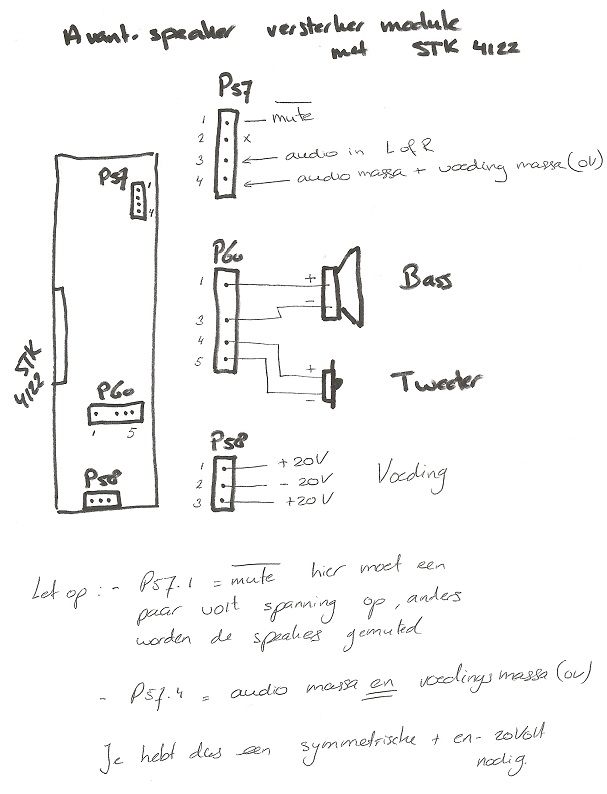
Firstly, I have managed to install Spotify on the Rasberry Pi board and got it to work via Wifi to send a signal out from the phono connector with variable volume set on the Spotify app on my phone. So, the easy part is now done… Now over to the difficulty part of connecting together a set of active speakers… I managed to find a wire diagram which is uploaded below which gave me some understanding.
From the Avant, I have harvested the speakers and the sound board (10). I have reconnected the speaker cables to the sound board as connected when in the TV on P77 and P78 connectors (also according to the diagram below). I managed to find a 20v 4A transformer which I connected to the board on P58. Assuming this is correct, I am then struggling to understand how I should connect the Rasberry Pi to the connectors in P57. Using L, R and GND does not work which makes me wonder if the setup is missing a component from the TV or I need other components to get it working.
any thoughts?
Attachments:
You must be logged in to view attached files.14 September 2024 at 07:08 #59066Madskp
GOLD MemberI would think that you also will need some kind of signal on the mute pin in P57. I think that the principle is that the speaker circitry is being held in a mute state until activated.
I do not have acces to any diagrams of the Avant, so I can not come closer than this. If you still have the other parts and can turn it on you could meassure the voltage on the mute signal when its in standby and when the TV is on
Location: Denmark
25 September 2024 at 15:13 #59396This diagram is from old forum.
Note: power supply is not 20v DC
It is -20v / +20v
You can translate the Dutch text if required.
25 September 2024 at 19:07 #59404I draw that once 😉
You need a symmetrical powersupply indeed.Location: Utrecht
25 September 2024 at 19:31 #59406Glitch
BRONZE Member<snip> I managed to find a wire diagram which is uploaded below which gave me some understanding. <snip>
any thoughts?
The datasheet for the STK amplifier module may give you clues about how to hook-up the amplifier board. It is usually worthwhile to examine the datasheet example circuits since it is common for OEM’s to implement them exactly (or very close). Make the STK module happy and you will have sound.
Glitch
-
AuthorPosts
- You must be logged in to reply to this topic.


