


Home › Forums › Product Discussion & Questions › BeoGram › Question About Beogram 8002 Recapping
- This topic has 67 replies, 5 voices, and was last updated 1 year, 1 month ago by
 marcham.
-
AuthorPosts
-
8 February 2025 at 01:24 #63560
 marchamBRONZE Member
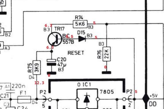
Hey, all. Replaced TR17, but nothing changed.
To confirm the current situation, the display shows four dots and pressing ‘Start’ displays ’33,’ but nothing starts up.
Also, to double check, should the state of each keyboard button be high by default at the CPU, then go low when pressed? That’s the current state at the moment.
Included some readings from the reset section below. It remains high at CPU pin 39 at all times.
Thanks!

Location: Pennsylvania, USA
Favourite Product: Beogram 3000
Signature: - Michael Archambault
My B&O Icons:
 11 February 2025 at 22:51 #63700marchamBRONZE Member
Bit of an update. After wondering why my progress regressed, I decided to go through and test the basics (aka power). I found that the 15V line wasn’t producing voltage and quickly traced it back to a loose connection on the P2 connector.
This harkens back to one of the original problems I had when I started working on the unit. Wires started coming loose from the P2 connector. I attempted to fix this by reinserting the wires and using hot glue to hold them in place. While ‘okay,’ this solution hasn’t been great and isn’t producing the most stable connection.
Does anyone have any recommendations on where to find replacement Molex connectors for the wires? I can’t find the exact replacement anywhere.
I also tried removing the metal pins from the connector to reattach the wires correctly, but I couldn’t remove them.
Thanks, all.
Location: Pennsylvania, USA
Favourite Product: Beogram 3000
Signature: - Michael Archambault
My B&O Icons:
13 February 2025 at 00:24 #63755You can get an extractor tool cheaply. – i.e. https://a.co/d/j3yLCnU. If you are trying to terminate the wires with new pins, that requires a special crimp tool and new pins and housings are available in kits.
14 February 2025 at 00:31 #63776marchamBRONZE MemberThanks, Mark! Someone on Reddit had suggested this as a replacement, so I’ll grab a few new connectors and clips.
https://www.digikey.com/en/products/detail/molex/0022012121/1090462
https://www.digikey.com/en/products/detail/molex/0008650805/1130600
Location: Pennsylvania, USA
Favourite Product: Beogram 3000
Signature: - Michael Archambault
My B&O Icons:
26 February 2025 at 04:13 #64073marchamBRONZE MemberHey, all.
Thanks for sticking with me on this multi-month journey; I’ve been learning more than you can imagine.
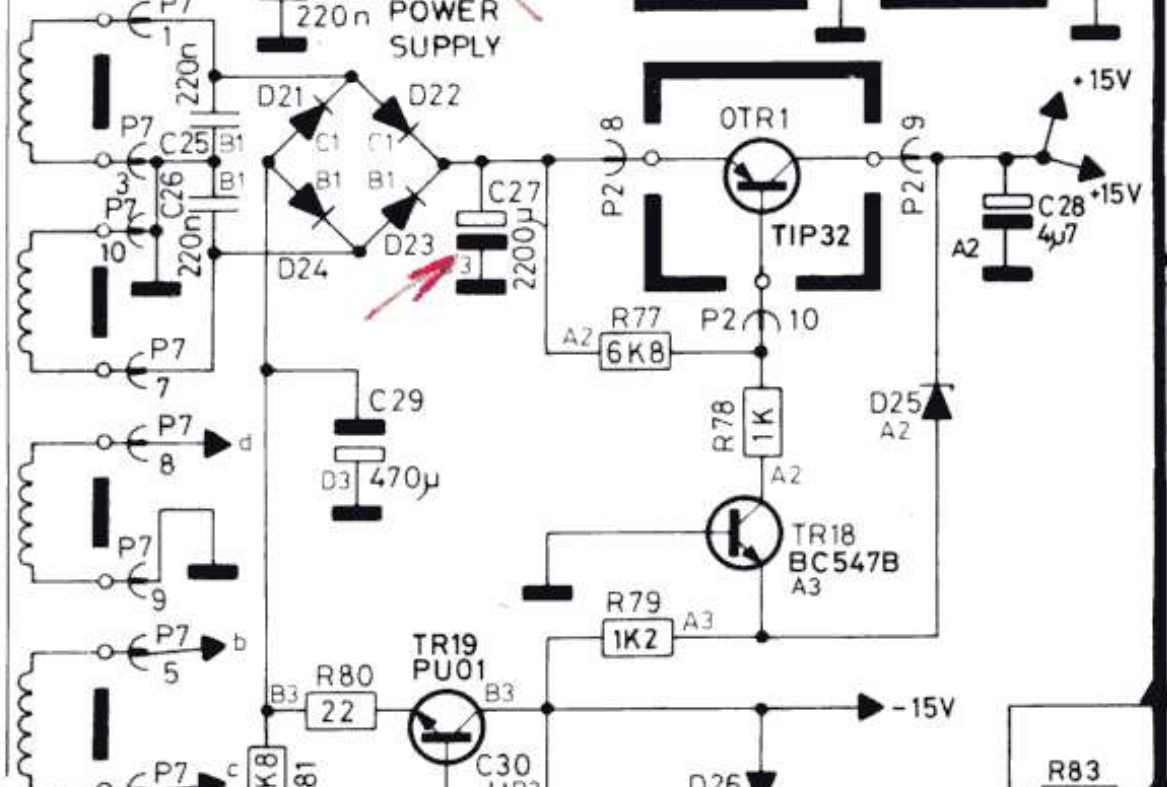
The good news is that I finally have a standby light after solving some communication issues between the PCB and PCB2 and fixing the bad Molex connectors. The ‘bad news’ is that I’m troubleshooting the 15V circuit and am a bit stuck.
I’m suddenly not getting a +15V signal, so I’m investigating the appropriate area of the circuit. I believed OTR1 (TIP32) might be bad, so I swapped it out with a brand-new TIP32C.
I get a solid 23V signal from D21-24, across the leg of C27, and straight to P2-8. However, the measurements of OTR1 show 23V at both the base and emitter. The collector and P2-9 are sitting at 0V.
I’ve swapped out OTR1 for another TIP32C, even though it tests fine and has the same result. I’ve even swapped out R77, thinking it could have been bad despite testing fine, but the issue remains.
Other notes of worth:
+ Measuring between P2-8 and P2-10 shows 6.8k Ohms as it should.
+ TR18 has 23V at its collector. 0V at the emitter and base. It recently tested fine.
+ Removing OTR1 and testing the board shows no issues with unexpected connectivity.
+ D25 is tested and working fine.
+ C27 and C28 test fine.What am I missing here? Is OTR1 at fault? Is the TIP32C not a solid replacement? I’m still trying to wrangle proper resistor drops, as both sides of R77 measure about the same (23V), so it doesn’t seem to do much.
Thanks, all.

Attachments:
You must be logged in to view attached files.Location: Pennsylvania, USA
Favourite Product: Beogram 3000
Signature: - Michael Archambault
My B&O Icons:
14 March 2025 at 03:54 #64491marchamBRONZE MemberEvening, all.
I was able to track down the issue for my last problem and now have my +15V, -15V, and +5V rails. 👍
However, I still have problems with the unit and suspect the CPU. Current problems include a constantly spinning turntable, no response to keyboard input, and a display that goes between showing one dot and multiple dots. I’ve confirmed the keyboard presses do take the appropriate pins low.
Here are my readings; does all look okay from the CPU side of things?
- PIN # 1, 5V, DATA LINK
- PIN # 2, 5V, KB: PLAY
- PIN # 3, 5V, KB: STOP
- PIN # 4, 5V, KB: DOWN
- PIN # 5, 5V, KB: UP
- PIN # 6, 5V, KB: 45
- PIN # 7, 5V, KB: 33
- PIN # 8, 5V, KB: PAUSE
- PIN # 9, 4V, DATA LINK
- PIN # 10, 2V, CRYSTAL
- PIN # 11, 2.3V, CRYSTAL
- PIN # 12, 0V, GROUND
- PIN # 13, 5V, DIGIT SELECT OUT
- PIN # 14, 5V, DIGIT SELECT OUT
- PIN # 15, 0V, DIGIT SELECT OUT
- PIN # 16, 5V, DIGIT SELECT OUT
- PIN # 17, 5V, BCD OUT
- PIN # 18, 5V, BCD OUT
- PIN # 19, 5V, BCD OUT
- PIN # 20, 5V, BCD OUT
- PIN # 21, 5V, ?
- PIN # 22, 3.5V, INDICATOR
- PIN # 23, 5V, KB: TURN
- PIN # 24, 2.5V, LIFT
- PIN # 25, 5V, <<
- PIN # 26, 5V, >>
- PIN # 27, 5V, SLOW <<
- PIN # 28, 3V, SLIDE TACHO
- PIN # 29, 3V, SLIDE TACHO
- PIN # 30, 5V, 5V
- PIN # 31, 0V, LIFT MANUAL
- PIN # 32, 0V, SO
- PIN # 33, 5V, DISC DETECTOR
- PIN # 34, 5V, SLOW DOWN
- PIN # 35, 5V, FAST UP
- PIN # 36, 0V, SLOW UP
- PIN # 37, 5V, FAST DOWN
- PIN # 38, 2.5V, POWER ON/OFF
- PIN # 39, 4.5V, RESET
- PIN # 40, 0V, SPEED SENSOR
Note that PIN 38 is sitting at 2.5V (is that correct?); I thought it should be either 0V or 5V.
The same comment goes for a few other pins. I thought it would be either low (0V) or high (5V).
Thanks.
Location: Pennsylvania, USA
Favourite Product: Beogram 3000
Signature: - Michael Archambault
My B&O Icons:
14 March 2025 at 14:58 #64492GlitchBRONZE MemberIt is good to hear that you are making progress.
Have you hooked up an oscilloscope to the display strobe pins (13-16)? If so, what are they doing? The strobe signals are usually a good place to check for signs of life in the CPU.
I was able to track down the issue for my last problem and now have my +15V, -15V, and +5V rails.
What was the issue with the voltage rails?
Glitch
15 March 2025 at 04:25 #64497marchamBRONZE MemberHey, Glitch. Yep, I’m stubborn and refuse to put this machine down. 😅
Checked out the display strobe pins on the scope, and don’t get anything besides a flat 5V signal.

The issue with -15V rail was down to a bad TR19. I had replaced the TR19 with a new PU01, but turns out I must have gotten a counterfeit from eBay. When popping it in my component tester, it recognized the transistor, but backwards; as in the case was labeled EBC, but was actually arranged CBE. I flipped it around, and it seems to work without issue for now. Still going to get a proper replacement from Danish Sound Shop in the future.
Location: Pennsylvania, USA
Favourite Product: Beogram 3000
Signature: - Michael Archambault
My B&O Icons:
-
AuthorPosts


- You must be logged in to reply to this topic.