


Home › Forums › Product Discussion & Questions › BeoGram › Question About Beogram 8002 Recapping
- This topic has 67 replies, 5 voices, and was last updated 1 year ago by
 marcham.
-
AuthorPosts
-
17 October 2024 at 15:31 #60226
 GlitchBRONZE Member
When you say to avoid the urge to debug by part swapping, how would I test components properly then? In this case, I was going to try to trace the failure point from the power supply pins, where I can now detect continuity between two pin pairs, unplugging components as I test them. Is there a better option?
Apologies in advance it you already know this… What I consider “debugging by part swapping” would be something like blindly replacing any component because it might be the one causing the problem. For example, if you aren’t getting a good 5v signal, you could replace D16 to D19 with new parts. It is unlikely that this would fix the problem. Instead, I think that it is better to understand how the power supply works, then devise and run tests to verify it it is working or not. The 5v supply is very similar to that described here. Using your meter, check to see if the voltages and waveforms are what they should be. If not, the problem could be in the circuit or external to it. Isolating the power circuit would be the next step. I would start by removing connector P2 and verifying the output of the rectifier and transformer. If that checks out, remove P2-2 (pin2 2 of connector 2) and reinstall the connector. This isolates most of the 5v power supply from the external circuit (it also provides a convenient place to measure 5v current draw later). Retest the 5v power signals. Still no joy? The problem must be in either the power supply circuit or reset circuit. Lifting a leg of R75 further isolates the power supply from anything else. If the power supply still doesn’t work, there are only a couple of parts that could be the problem and it should be pretty obvious which one(s) based on the meter readings. Now is the time to start removing, testing, and possibly replacing individual components (based on data instead of hunches). I purposefully went into painful detail here to illustrate an approach that is based on 1) understanding how the circuit works, 2) measuring to verify proper operation and 3) isolating the circuit for ease of debugging. Also, note that there was a minimal amount of soldering involved. Much of what I described above is implicit in the advice that you got from others. Hopefully my explanation provides insights into why things are being suggested.
Based on your posts it sounds like you are getting more serious about this hobby. Check out the Digilent Analog Discovery. It might be useful to you. In general, anything that it does can be done better with dedicated bench equipment. However, everything that it does, it does well and is often all that is needed.
Glitch
6 November 2024 at 05:20 #60741marchamBRONZE MemberThanks, Glitch; I appreciate the feedback and help along the way!
While I’ve made mistakes throughout the process, and the board has certainly seen better days visually, I’ve taken the time to improve my soldering skills and learn how to better care for my equipment. Funny enough, I have quite a bit of repair gear sitting around now (even if I don’t know how to use it all 100%): a soldering station, variable power supply, multimeter, component tester, tone generator, and oscilloscope. Each project I tackle has allowed me to move forward with more knowledge and learn to use more of my gear. In the meantime, I’ve brought a Beocord 9000 and a pair of Beovox S75 speakers back to life, so that’s been a nice win!
The partial good news: After investigating the board, reflowing joints, and replacing a shot resistor (that component tester is fantastic), the machine shows the standby light when fed power and doesn’t blow a fuse when powered on! The 8002 is now back to the state I received it in, but with new, fresh caps that don’t cause the tonearm to move inward 1 inch and then return when pressing Play. However, it is not all finished, as two other issues have appeared.
New issue #1 popping up: Pressing turn will spin the turntable without issue, and pressing stop will bring it to an end. However, the Beogram will not play. When pressing Play, the tonearm moves inward and does not stop even when it reaches the spindle. The motor continues to spin, the belt slipping on the spindle as it tries to continue moving it inward. I searched the Beoparts website (now: Danish Sound Parts) and found they sell an IR LED for the Beogram. They note that when this component fails, “the Beogram will not stop the carriages’ travel at the beginning of the record, but instead keep traveling leftwards until it can’t go any further, so I think this could be my fix.
New issue #2 popping up: A second issue (which might be causing the first) has popped up, too. When P4 is plugged in, and the board is prodded in the same area (as P4), one of two things happens: the platter will change its movement (stopping or starting), or the Beogram will blow its fuse. The latter occurs most often. Do you know what could be causing the issue in this area? I don’t see any obvious solder cracks or visually failed components.
Thanks again!
Location: Pennsylvania, USA
Favourite Product: Beogram 3000
Signature: - Michael Archambault
My B&O Icons:
 6 November 2024 at 15:45 #60744GlitchBRONZE Member
I’ve taken the time to improve my soldering skills and learn how to better care for my equipment.
That should help with making the rest of the debugging more effective. At the very least, it should make working on things more enjoyable.
Funny enough, I have quite a bit of repair gear sitting around now (even if I don’t know how to use it all 100%): a soldering station, variable power supply, multimeter, component tester, tone generator, and oscilloscope.
That is good to know. It is helpful to people trying to give advice to understand what resources (both skill level & equipment) are available.
Each project I tackle has allowed me to move forward with more knowledge and learn to use more of my gear. In the meantime, I’ve brought a Beocord 9000 and a pair of Beovox S75 speakers back to life, so that’s been a nice win!
It sounds like you are taking the right approach. Even if a repair doesn’t turn out to be successful, if you learned something in the process, it is a win.
The partial good news: After investigating the board, reflowing joints, and replacing a shot resistor (that component tester is fantastic), the machine shows the standby light when fed power and doesn’t blow a fuse when powered on! The 8002 is now back to the state I received it in, but with new, fresh caps that don’t cause the tonearm to move inward 1 inch and then return when pressing Play. However, it is not all finished, as two other issues have appeared.
That’s great news. I’m sure it is a big relief to you.
New issue #1 popping up: Pressing turn will spin the turntable without issue, and pressing stop will bring it to an end. However, the Beogram will not play. When pressing Play, the tonearm moves inward and does not stop even when it reaches the spindle. The motor continues to spin, the belt slipping on the spindle as it tries to continue moving it inward. I searched the Beoparts website (now: Danish Sound Parts) and found they sell an IR LED for the Beogram. They note that when this component fails, “the Beogram will not stop the carriages’ travel at the beginning of the record, but instead keep traveling leftwards until it can’t go any further, so I think this could be my fix.
This could be example where you could resist “parts swapping”. One could just order the part from Beoparts (now: Danish Sound Parts) and swap parts. There is a decent chance that this will fix the issue. Alternatively, you could run tests to check if the circuit is operating as expected. Use the camera of your cell phone to check if the IR (transmitter) LED is lighting up. If the LED isn’t lit, it is getting power or is the component bad? If the LED is lit, then hook up your oscilloscope to see if the IR receiver is reacting to changes in the light received. These circuits usually work by blocking or passing light between the two parts. You can use B&O’s “light blockers” or do it manually by inserting something like a piece of cardboard. The general idea is to think of and run tests that enable making better (data driven) decisions on how to proceed. If you do end up replacing the part and the machine starts to work, run the same tests again on the now working machine to gain the experience of what the signals should look like. BTW, a second, properly working, machine is an invaluable luxury for debugging purposes (if you are looking for an excuse to buy more B&O stuff 😉 ).
New issue #2 popping up: A second issue (which might be causing the first) has popped up, too. When P4 is plugged in, and the board is prodded in the same area (as P4), one of two things happens: the platter will change its movement (stopping or starting), or the Beogram will blow its fuse. The latter occurs most often. Do you know what could be causing the issue in this area? I don’t see any obvious solder cracks or visually failed components.
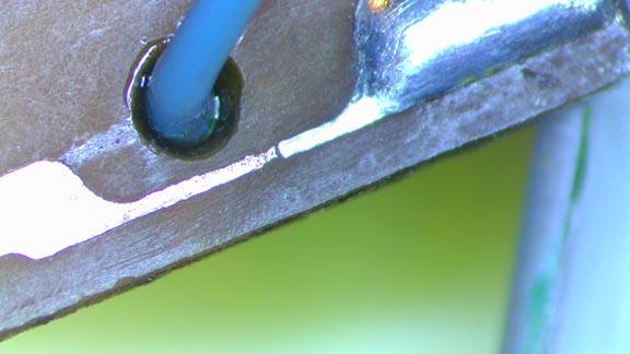
The problem could be a number of things. One guess would be a related to the motor control circuit not always getting a clean feedback signal. It could be a cracked trace that is hard to see. Below is an example of one that took me a while to find.

The open trace was under the solder flux residue and not apparent until I cleaned the board. I wouldn’t have known to look in this spot unless I ran tests that indicated that there was an opening “somewhere” along the circuit that was causing the signal not to get through. I’ve found other really unusual things causing open/intermittent circuits like broken pins inside of a connector and a failure of plating of an edge connector pin. Hook up your oscilloscope to the tachodisc receiver and observe the signal when the motor is turning properly. Prod the board to recreate the failure and observe the signal. Don’t be afraid to change the place where you are making the measurement (i.e. on either side of the connector along the signal path) as this can often provide clues. Another debugging method possibility is to hook up your scope to monitor voltages and see if they change while prodding the board.
It is worthwhile to pay attention to the information included on the schematic. If B&O went through the trouble of indicating a voltage value or including a plot of what a signal should look like, it is a good idea to make the measurement for yourself. This is one of those things that seems like it would be obvious, but people often miss. Also, the passing along the results of those tests (both good and bad) is helpful to those trying to provide debugging advice.
Glitch
15 December 2024 at 05:55 #61629marchamBRONZE MemberHey, Glitch (and others),
It has been a while since I popped into this thread, as I’ve had some of my projects on hold. I was waiting on parts for the Beogram and then had to solve an issue with the ribbon cable connecting PCB2. Luckily, all that has been handled, and I’m down to troubleshooting what is hopefully the last issue, and I need a bit of assistance.
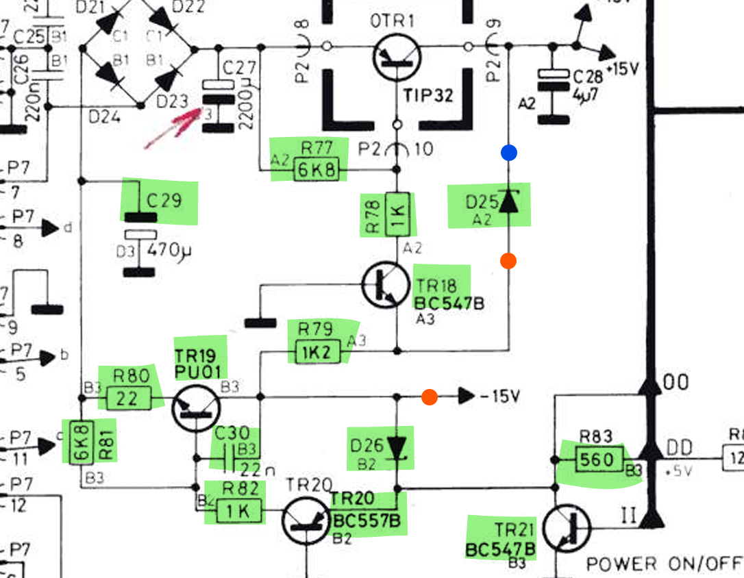
Long story short, there is an issue with my -15V rail; I’m getting 5V and 15V fine, but the -15V is nonexistent. I’ve uploaded a photo of the schematic for additional detail. Red spots are where I have tested for voltage and only received around .75 V. The blue spot is an example of a place I tested and received +15V. The components highlighted in green appear to be working when tested.

Any thoughts? I figured if there were an issue with the 15V rail, I would find it in one of these highlighted components. Any advice?
Thanks, all,
Location: Pennsylvania, USA
Favourite Product: Beogram 3000
Signature: - Michael Archambault
My B&O Icons:
16 December 2024 at 14:34 #61668GlitchBRONZE MemberI would start by checking the “POWER ON/OFF” signal (it should switch between ~0v & ~5v, check it at TR21 and at the CPU), then C29, then check the voltages around the parts that you have highlighted. I’ve found that writing the measured voltages (both in STANDBY and ON) on a copy of the schematic can sometimes be helpful. This information would be also be useful to anyone trying to provide advice.
Glitch
19 December 2024 at 05:08 #61731marchamBRONZE MemberThanks for the info, Glitch. Checking at TR21, there is no voltage when the Beogram is on or off. If I check pin 38 of the CPU, the voltage is 2.5V when off and 0V when switched on. I can confirm that 5V is making it to the CPU at pin 30. As for C29, the voltage stays stable at all times around 24V. I’m not sure if this helps illuminate a picture.
I’ll try to test some other areas within the circuit, but hopefully, the above is a clue. Seeing it connected in the block diagram, I also tested transistors TR6, TR22, and TR23 — all look good.
I’m trying to find a fault that would cause the display to always show four red dots and the table to constantly spin at a slow speed, even when off.
Location: Pennsylvania, USA
Favourite Product: Beogram 3000
Signature: - Michael Archambault
My B&O Icons:
26 December 2024 at 19:35 #61935marchamBRONZE MemberAfternoon, all. Hope everyone is having a good holiday.
I had the time to dive in and take more voltage readings.

As someone who doesn’t know exactly how a circuit flips a voltage from 15V to -15V, I would say that something looks a bit off around TR18, even though that transistor tested well. But, again, what do I know? 🙂
Any insight appreciated. Thanks, all!
Location: Pennsylvania, USA
Favourite Product: Beogram 3000
Signature: - Michael Archambault
My B&O Icons:
26 December 2024 at 23:25 #61941GlitchBRONZE MemberAs someone who doesn’t know exactly how a circuit flips a voltage from 15V to -15V, I would say that something looks a bit off around TR18, even though that transistor tested well. But, again, what do I know? 🙂
The circuit doesn’t “flip” the voltage. It regulates from the negative side of the bridge rectifier. You have -23v there so you are off to a good start. I’m not sure exactly sure what TR18 does. I’d have to think harder about the circuit than I’m willing to do right now. I believe that the key to your solution lies with the base of TR21. It should get pulled high by the CPU and enable the -15 supply. Verify that the connection between the two is solid.
As always, I could be wrong. I have a faint recollection of the POWER OFF/ON signal also controlling the +15v power. I could also be thinking of another piece of equipment.
Are the voltage measurements taken in ON or Standby?
Glitch
27 December 2024 at 06:57 #61946marchamBRONZE MemberHey Glitch, Thanks for the explanation; that makes sense.
Looking into TR21, the signal sits at .71V in standby and drops to .08V when switched on with the tonearm in motion. All readings in the diagram were taken in standby mode.
To help visually, I recorded a short two-minute video.
Location: Pennsylvania, USA
Favourite Product: Beogram 3000
Signature: - Michael Archambault
My B&O Icons:
4 January 2025 at 23:21 #62286marchamBRONZE MemberJust popping in with an update.
Still at the same point but been poking around the board and reading voltages.
I noticed that the main chip’s voltage on pin #38 (on/off) swaps between 0V and 2.5V. However, the chip seems to be getting its primary 5V at pin #30 without issue, so could the chip be the issue in any way? I tried reseating it, but it did not change.
Poking around TR19 and TR21 trying to figure out why there is still no -15V signal. I feel that’s the heart of the issue.
Thanks, all.
Location: Pennsylvania, USA
Favourite Product: Beogram 3000
Signature: - Michael Archambault
My B&O Icons:
17 January 2025 at 04:30 #62817marchamBRONZE MemberI’m adding more information in the hope that someone can help me with the missing -15V rail. Three lines leading away from the power section, near TR21, are 00, DD, and II.
Tracing down II leads to the CPU outputting either 0V or 2.5V via the On/Off pin.
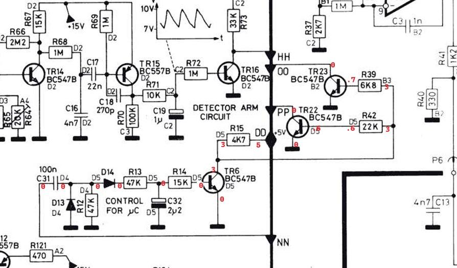
DD connects to the +5V supply and leads to an upper section that I have included below with readings. 00 also leads to this upper section, and I have included the readings as well.
From 00 is PP, which leads to the braking circuit. It feels like I’m getting close, as another problem right now is a constantly spinning platter.
From DD is NN, but that appears to lead to ground.
As always, any help is appreciated, thanks!

Location: Pennsylvania, USA
Favourite Product: Beogram 3000
Signature: - Michael Archambault
My B&O Icons:
17 January 2025 at 07:50 #62818DillenModeratorIf the platter spins in standby check 0TR1 (TIP32A).
I have seen more than one case of it being bad, not closing the 15V down but instead leaving it hovering around 5-6V.And check copper traces in the -15V regulator area.
The traces are known to develop cracks near solder pads, that can be very difficult to spot. Particularly if your soldering iron is a bit too hot.Martin
18 January 2025 at 05:08 #62847marchamBRONZE MemberHey Martin, I really appreciate the response.
Let me know if I’m misunderstanding your suggestion, but the 15V rail seems to work perfectly; it’s only the -15V that is MIA.
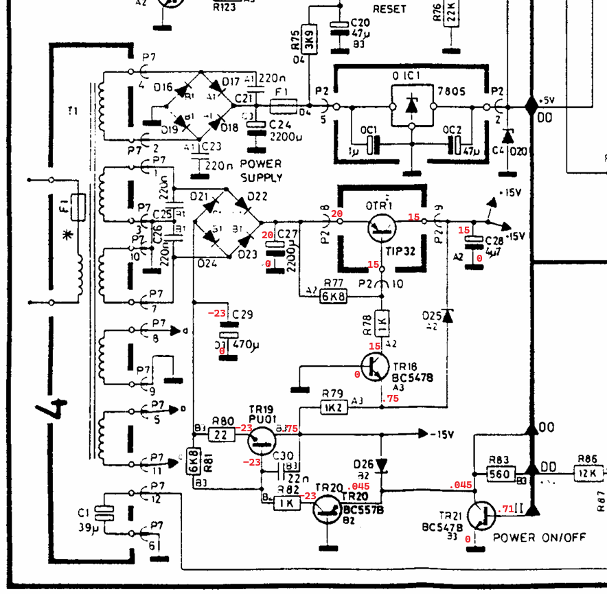
Here is a copy of the circuit readings I previously provided. 0TR1 seems to be working fine.
As for a break, do you see anything odd within the circuit readings?
Hoping between these and the section included above, they hold a clue.
Thanks again!
Location: Pennsylvania, USA
Favourite Product: Beogram 3000
Signature: - Michael Archambault
My B&O Icons:
21 January 2025 at 18:58 #62968DillenModerator0TR1 provides a good 15V, yes.
But does it close completely in standby?Martin
22 January 2025 at 03:22 #62984marchamBRONZE MemberThanks for clarifying, Dillen.
These readings were taken in the standby state.
Here is how the states change between standby on/off:
Standby: E:20V, B:14V, C:14V
On: E:20V, B:13V, C:13V
I should note, the platter spinning in standby is not a ‘slow’ spin, but quite fast.
Additionally, the Play/Stop buttons work intermittently.
Location: Pennsylvania, USA
Favourite Product: Beogram 3000
Signature: - Michael Archambault
My B&O Icons:
22 January 2025 at 16:10 #63002DillenModeratorIf these measurements were taken on 0TR1, replace it!
Martin
22 January 2025 at 22:01 #63006marchamBRONZE MemberUnderstood, replacing it. Thank you, Dillen! I will report back once the replacement part has arrived and been installed.
If you have a moment for me to learn, why this recommendation? In my beginner’s eyes, it appears 0TR1 is working right, and the wrong voltage is being sent to the base during standby, meaning a different component is at fault. So why replace OTR1?
Thanks as always!
Location: Pennsylvania, USA
Favourite Product: Beogram 3000
Signature: - Michael Archambault
My B&O Icons:
5 February 2025 at 03:53 #63414marchamBRONZE MemberHey, all! The swap of 01C1 was successful in moving forward the repair. Everything receives the correct power: 5V, 15V, and -15V. However, the unit doesn’t want to start up properly. After experimenting, I found that the unit has a constant 5V at pin #39 (reset); I assume this should go low when switched on.
I can confirm that hitting the ‘Play’ button does reach the CPU. I dove into the reset circuit, but everything seems fine. All resistors test fine, the cap (C20) tests fine, the diode (D15) is OK, and so is the transistor (TR17). The base gets a constant 5V, while the emitter and collector are around 6V.
I’m a bit confused about this. I assume that the base shouldn’t be 5V at all times, but where does the signal come from? The base only goes to D15, directly from around P2(2), which seems like it would always have a constant 5V. What am I missing?
Thanks!
Location: Pennsylvania, USA
Favourite Product: Beogram 3000
Signature: - Michael Archambault
My B&O Icons:
5 February 2025 at 06:19 #63415DillenModeratorIf you have a moment for me to learn, why this recommendation?
Sure.
An emitter-base voltage difference of several volts on a PNP transistor points to a missing B_E connection.
Similarly, the exact same voltages found on base and collector could point to an internal short here.Martin
7 February 2025 at 02:19 #63488marchamBRONZE MemberHey Dillen. Thanks, appreciated!
I’ll have to research my understanding of transistors, as I thought TR17 looked good.
I thought that if the B was powered (5V), C and E should be open with the same voltage (6V).
I ordered a new bc557b transistor and it will be here tomorrow to swap out.
Thanks again.
Location: Pennsylvania, USA
Favourite Product: Beogram 3000
Signature: - Michael Archambault
My B&O Icons:
-
AuthorPosts


- You must be logged in to reply to this topic.