


Home › Forums › Product Discussion & Questions › BeoGram › Question About Beogram 8002 Recapping
- This topic has 67 replies, 5 voices, and was last updated 1 year, 4 months ago by
 marcham.
-
AuthorPosts
-
9 October 2024 at 23:29 #59981
 marchamBRONZE Member
The proper fuses (T300 mA/250V) arrived today; unfortunately, they blow when the power supply is connected to the board. The fuse is okay if I plug in the power supply without connecting it to the board, so I assume there is a short or something somewhere.
This is where my already limited knowledge hits a wall, so I’m hoping for any recommendations. My only thought would be to pull the caps for testing and then start testing the transistors and diodes. Any suggestions on where to start testing or specific components would be appreciated— any way to hunt this down without removing and testing so many components?

Thanks, all.
Location: Pennsylvania, USA
Favourite Product: Beogram 3000
Signature: - Michael Archambault
My B&O Icons:
 10 October 2024 at 00:07 #59984
I would start by leaving the supply disconnected and measuring resistance on the board side between each pair of windings pins looking for a short. Ex: P7 pins 2 and 4. Then you can desolder to find the shorted part.
10 October 2024 at 02:16 #59985marchamBRONZE MemberThanks. I checked for continuity between the following P7 pins, and everything seemed fine: 4-2, 1-3, 10-7, 8-9, 5-11, and 12-6. No buzzes or resistance was shown; it was completely open.
Out of curiosity, I unplugged everything from the board so only the power supply and the main board were connected; it tripped. So, it is something on the main board.
I did my best to test the diodes in the two bridge rectifiers, but everything seemed to flow only in one direction, which looked good.
I think something happened when C27 or C24 was installed incorrectly or backward. I looked over the board for any signs of damage, but everything looks good, so I’m still lost.
Thanks again,
Location: Pennsylvania, USA
Favourite Product: Beogram 3000
Signature: - Michael Archambault
My B&O Icons:
10 October 2024 at 06:00 #59986marchamBRONZE MemberUpdate: I retested the pins you suggested but left the other connectors plugged in. With this setup, pins P7-12 and P7-6 do have continuity.
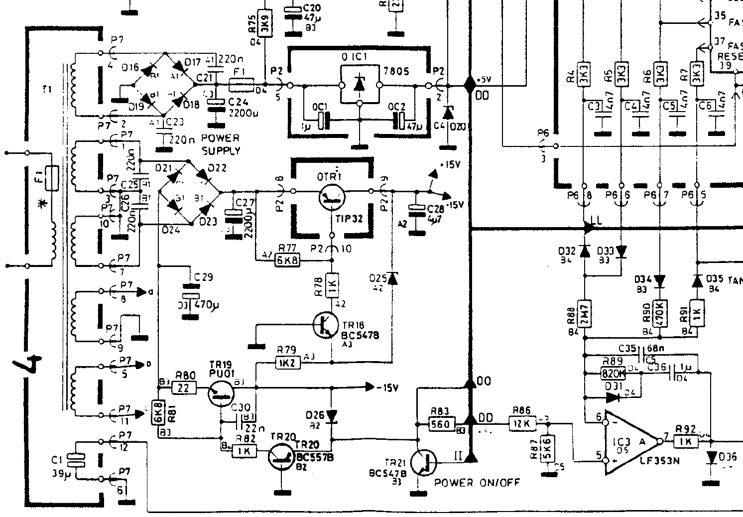
The schematic screenshot below shows where P7-12 leads; P7-6 goes to ground. The bottom-most path is from P-712, leading to D42 and a relay. Would you suggest following both paths and testing each component as I go, or is there a more efficient way to test?
Thanks!
Location: Pennsylvania, USA
Favourite Product: Beogram 3000
Signature: - Michael Archambault
My B&O Icons:
10 October 2024 at 11:38 #59991Hi
I’ll try to help a little bit.
P7 – 12 and P 7 – 6 go to ground because
P 7 – 6 is Ground
P 7 – 12 has a conection to ground via the motor coils ( 0 L 1) related Plug ( P 4 -2; P4 – 5) . Have not measured the coils so far but could be in around 200 or less Ohms.
So desolder one leg of D42 and check for a short.
A common issue, what I had already twice for what reason ever, is D 20.
This is a Z Diode 6,3 V and a protective diode for the 5V of Processor and so on.
In case of a overvoltage of the 5 V line this diode is shorted and the fuse could trip to protect the connected uPC and others.
So check D 20
Kind regards
Christian
10 October 2024 at 23:11 #60013Update: I retested the pins you suggested but left the other connectors plugged in. With this setup, pins P7-12 and P7-6 do have continuity. The schematic screenshot below shows where P7-12 leads; P7-6 goes to ground. The bottom-most path is from P-712, leading to D42 and a relay. Would you suggest following both paths and testing each component as I go, or is there a more efficient way to test? Thanks!
Yes, P7 is the only connector you should have removed. I would check for losing the short by selectively removing the gnd sides of D20, 0C1, 0C2 and 0IC1 to find the defect.
12 October 2024 at 03:45 #60042marchamBRONZE MemberThanks for the assistance, Spassmaker and Mark,
I checked D20 and D42, and both appear to operate as they should, with continuity in only one direction.
To double-check, is it normal or not to have continuity between P7-12 and P7-6? It sounds like I’m being told it’s normal due to the motor. This would make sense since the continuity between those two pins P7 pins only occurs when the P4 connector is plugged in.
Regarding checking 0c1, 0c2, and olc1, I’ve removed and checked these parts, which seems to operate fine. Although I don’t know if anything on this board would have an affect since the short occurs even with all connectors detached.
Shocked this simple capacitor swap out went down hill, but I can’t complain as I’m learning. Just want to find this short already.
Location: Pennsylvania, USA
Favourite Product: Beogram 3000
Signature: - Michael Archambault
My B&O Icons:
12 October 2024 at 05:19 #60043Putting C24 in backwards would definitely take out the F1 transformer fuse but could have damaged part of the diode bridge or transformer secondary. Are you getting AC voltages across each transformer secondary? If so when you connect P7 back only, what voltage are you seeing across C24?
12 October 2024 at 18:31 #60067marchamBRONZE MemberIt lives! Happy to say that I have found signs of life.
I was poking around the board and found some odd signs of continuity around the C27 cap, so I decided to do some investigating. I swapped out C27 for the original cap, and now I have power to the board. This tells me that my method of testing capacitors is obviously faulty.
My meter doesn’t have a proper capacitance mode, so I was simply seeing if the cap would recharge and then discharge. This means I’ll be treating myself to a new meter with a capacitance setting and maybe even a little component tester to prevent this in the future.
Anyway, not everything is working, but things are looking better. I still don’t get a standby LED, but a small light turns on near the tonearm and I can feel the motor warm up if I touch it. I’ve begun by testing all the caps to see the power flowing across them:
- C27: 22v
- C29: 23v
- C24: 12v
- 5v Regulator: 5v
The one cap that doesn’t have proper power flow is the cap on PCB2. When measuring, the cap has 0V across it with the machine off and 0.5V across it with the machine on. I’m assuming this means it isn’t a ribbon connection problem. I also followed Beolover’s advice of snipping the ribbon to make it fit into the connectors better, and it does sit very firmly now.
I’ll see if I can work backwards, discovering why that cap on PCB2 isn’t getting the proper power, but if anyone has any advice in the meantime, feel free to let me know. Thanks, all!
Location: Pennsylvania, USA
Favourite Product: Beogram 3000
Signature: - Michael Archambault
My B&O Icons:
12 October 2024 at 20:16 #60083marchamBRONZE MemberHad a bit more time to test around with the circuit. I can tell that the 5 volt regulator is outputting correctly and it makes its way to the main board via P2. I can then test the connector that goes to the PCB2 (via P6) and this is where things get odd.
The first pin (P6-1) should send out 5 volts to PCB 2, but it only does this when PCB2 is unplugged. If I test with PCB2 plugged in, the voltage on that pin drops to only .5 volts.
I visually examined PCB2 and I don’t see anything that seems to be improper. I also already replaced the capacitor on that board, which was a pain, but it seems to have been installed correctly. Before anyone asks, yes, I did get the solder on the top side of the negative leg of the cap.
Any thoughts what could be happening here? Thanks.
Location: Pennsylvania, USA
Favourite Product: Beogram 3000
Signature: - Michael Archambault
My B&O Icons:
12 October 2024 at 21:17 #60094This is where it gets tough as you may be hitting your original problem. I would check how much current you are drawing on P6-1 as you may have a bad regulator. Normally F1 (800ma) would blow if there was a large draw due to a shorted transistor such as the Lift driver TR9. Also is it at .5v just plugged in?
12 October 2024 at 22:33 #60097marchamBRONZE MemberI’m wondering if it’s the original problem, because the original problem at least had the standby light come on. That’s why I’m going to double check that the capacitor swap out didn’t mess something up, but didn’t see anything my first look.
But yes, if PCB2 is disconnected then at P6-1 I get 5 volts. As soon as I plug in PCB2 via the ribbon connector, it drops to .5 volts.
Location: Pennsylvania, USA
Favourite Product: Beogram 3000
Signature: - Michael Archambault
My B&O Icons:
13 October 2024 at 04:08 #60098The 7805 regulator can source more than 1A of current if working properly which is more than enough to blow the fuse before its short-circuit protection kicks in. I would confirm by measuring the output current when you plug the TT in and see if it exceeds 1A before dropping. If it doesn’t I would replace the regulator. If it does you are not going to have to start disconnecting 5v loads on the board and testing for 5v.
13 October 2024 at 06:08 #60099marchamBRONZE MemberMark, do you measure the regulator’s current the same way you measure voltage?
When connecting my negative probe to ground and the red probe to the regulator output, I can measure 5V, but when I switch it over to the Amp setting on my multimeter, I get nothing, 0 Amps. This is the same with PCB2 plugged in or unplugged.
Is this not the proper way to test it? Thanks!
Location: Pennsylvania, USA
Favourite Product: Beogram 3000
Signature: - Michael Archambault
My B&O Icons:
13 October 2024 at 21:42 #60121You measure current by putting your meter in series with the circuit. This means disconnecting the regulator output, soldering a jumper and using your probes in series. If you have alligator clip ends even better.
14 October 2024 at 03:21 #60127marchamBRONZE MemberThanks, Marc.
Without PCB2 plugged in I get 8.53. When I plug PCB2 into the main board, it drops to 7.57. I’m measuring between the 5v regulator output leg and the board.
Location: Pennsylvania, USA
Favourite Product: Beogram 3000
Signature: - Michael Archambault
My B&O Icons:
15 October 2024 at 03:49 #60160I’m afraid that reading does not make sense assuming you are measuring mAs. What you are looking for is not the steady-state reading but a current jump as you plug it in. I would use a second meter or Oscope to catch the drop in voltage at the time. At this point given your limits and these imperfect medium, I would replace the regulator just to rule it out as it’s very cheap.
16 October 2024 at 03:35 #60179marchamBRONZE MemberI discovered that the odd reading had something to do with the black connector on the board for PCB2. With a bit of pressure applied, it did indeed show the amps increase to a healthy sub-100 mA level. I decided to re-solder the connector, but unfortunately, an ultra-small solder bridge caused two pins to connect and a short to occur. So, now I’m tracing down another short. To make it worse, I’m not sure which two pins connected.
Rather than bother everyone here about it, I’ve decided to upgrade my equipment to a proper multimeter with capacitance testing, grab a small component tester, and an ESR meter. Hopefully, this will help me track down the problem with greater ease, following the schematic.
And before the suggestion comes through, yes, I would very much prefer to send this board to a trained repair specialist. But my budget does not really account for that. I’m assuming it would be hundreds of dollars to have this board looked at and repaired. If anyone knows that that’s not the case, please feel free to let me know.
If I can get this new issue fix, I may pop back in for help with the original problem. Thanks again.
Location: Pennsylvania, USA
Favourite Product: Beogram 3000
Signature: - Michael Archambault
My B&O Icons:
16 October 2024 at 15:52 #60197GlitchBRONZE MemberI’ve decided to upgrade my equipment to a proper multimeter with capacitance testing, grab a small component tester, and an ESR meter. Hopefully, this will help me track down the problem with greater ease, following the schematic.
Also, magnification and lighting is often overlooked as a debugging tool. I bought a stereo-microscope (a.k.a. inspection scope) to help me do SMD repairs. I was surprised to learn how useful that it was for debugging through-hole boards like what are in the BG8002. Careful inspection under good lighting can easily reveal solder bridges, cracked solder joints and traces, stray solder balls, bent and shorted component leads, etc. I consider the usefulness of an inspection scope to be right up there with a oscilloscope or multimeter.
Of course, even a decent, Chinese made (relatively inexpensive) stereo-microscope, like the Amscope, is cost prohibitive to most hobbyists. Alternatives are taking pictures with a camera (macro mode if possible) and viewing the pictures on a big monitor or USB microscopes that display on a big monitor. Scanning the board on a flatbed scanner and (you guessed it) viewing the results in on big monitor can also be very helpful if the scanner has a good depth-of-field.
The advantage of a stereo-microscope over the alternatives is that one can do live work under magnification without losing depth perception.
On a related note… I thought I was “really good” at soldering until I went back and examined my old work under the microscope. My work wasn’t that bad, but has definitely improved now that I can really see what I am doing.
I suggest that you really carefully inspect the boards for “mechanical issues”. Look for cracks, bridges, and now, places that may have been overheated. Go over the boards inch by inch. Inspect everything, not just where you worked. Avoid the urge to debug by part swapping. Every time one removes and replaces a part there is a chance of damaging the circuit board, even if good technique is used. Test any new parts before installing on the board, especially Chinese made ones or any components that could be counterfeit.
Don’t hesitate to ask if you have questions on interpreting the schematic or don’t understand how a circuit works. There many here (including myself) that would be happy to help. There are also many other general electronics repair resources out there. My experience with B&O equipment is that the basic circuitry isn’t much different than anything else out there. However, there is usually “more of it” to support the “B&O magic” features and there can be interdependencies that aren’t obvious. The good new is that if you can fix the basic functionality (like a light sensor not working or a switch not making contact, etc.) the interdependencies usually take care of themselves.
I wish you the best of luck with your repair.
Glitch
17 October 2024 at 04:11 #60215marchamBRONZE MemberThanks, Glitch.
I appreciate you taking the time to share your experience. I’m looking forward to the upgraded multimeter and component tester arriving tomorrow. I also have some new soldering iron tips coming, as the old ones were past their prime and causing heating issues. Luckily, I have a USB microscope, so I’ll take that out and use it to examine the board and double-check any future fixes.
When you say to avoid the urge to debug by part swapping, how would I test components properly then? In this case, I was going to try to trace the failure point from the power supply pins, where I can now detect continuity between two pin pairs, unplugging components as I test them. Is there a better option?
I’ll be sure to ask questions as I go. I’m busy this week, so all the fun might have to wait until next, but I’m looking forward to it. Frustrated since an electronic failure hasn’t happened to me like this in the past. I have a few B&O things to work on, and this was supposed to be the easy cap swap out, but oh well! Thanks again!
Location: Pennsylvania, USA
Favourite Product: Beogram 3000
Signature: - Michael Archambault
My B&O Icons:
-
AuthorPosts


- You must be logged in to reply to this topic.