Home › Forums › Product Discussion & Questions › Other › On the workbench: a B&O TG7 Oscillator
- This topic has 2 replies, 2 voices, and was last updated 1 year, 5 months ago by

-
AuthorPosts
-
3 August 2024 at 15:16 #57966
 BRONZE Member
Hello.
A section of B&O products rarely seen here so let’s give it some screen-time…
Amongst the usual B&O stuff, I’ve been slowly collecting a small selection of B&O’s test equipment (that they produced from somewhere around 1970’s up until the late 1980’s, see: https://archivedforum2.beoworld.org/forums/p/4460/40009.aspx#40009). I have two bench power supplies (SN16a and SN17) and two multimeters (RV7 and RV9a), all in this lovely blue-case styling.
Couple of weeks ago I came across a TG7 Oscillator on eBay, sold for a reasonable price, described as “works badly” which was somewhat intriguing… (At the time of posting this, the same seller has some more of these still for sale on eBay).
When I received the parcel (nicely packaged) I noted the following issues:
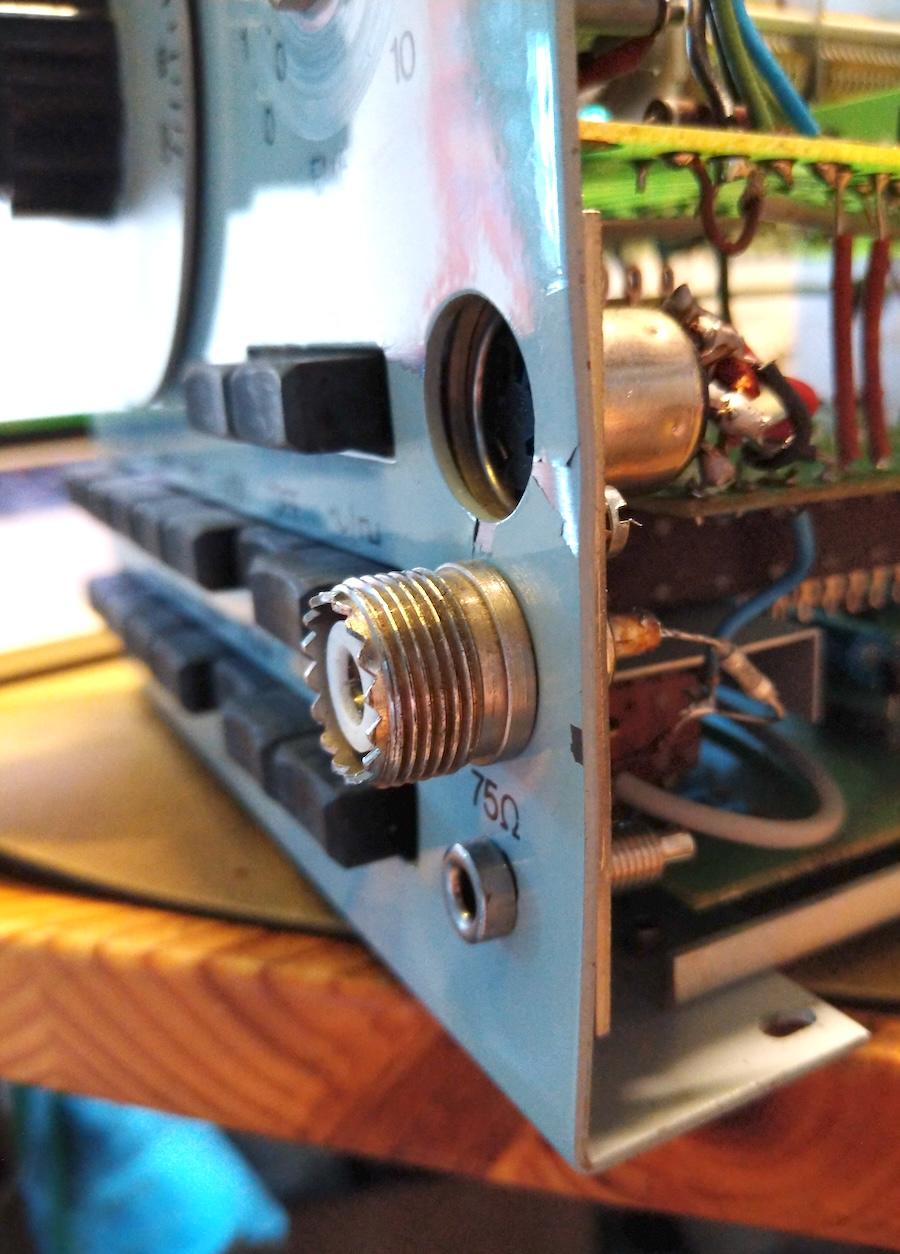
- (A fact that I somewhat missed from the pics) was that the bottom-right corner of the front panel had a big dent. I guess the unit has been hit or dropped and the force hitting the output connector and bending the edge of the front panel.
- Due to the bent front panel, some of the push-buttons would not move freely (or at all).
- The big frequency adjust dial was not moving right; turning it clockwise it would mechanically hit a stop at 70/100 and go below-scale on the other end.
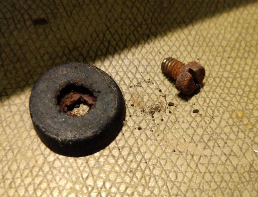
- One of the bottom rubber feet and screw was missing and the others badly degraded and their screws rusted.
- A black cover plate was missing from the amplitude adjust knob.
- I was able to power the unit on (after having had a preliminary look inside) and I did have some output, so at least there was life.
Fortunately, the service manual is available online: https://www.peel.dk/B&O/pdf/TG7%20%28komplet%20manual%29.pdf
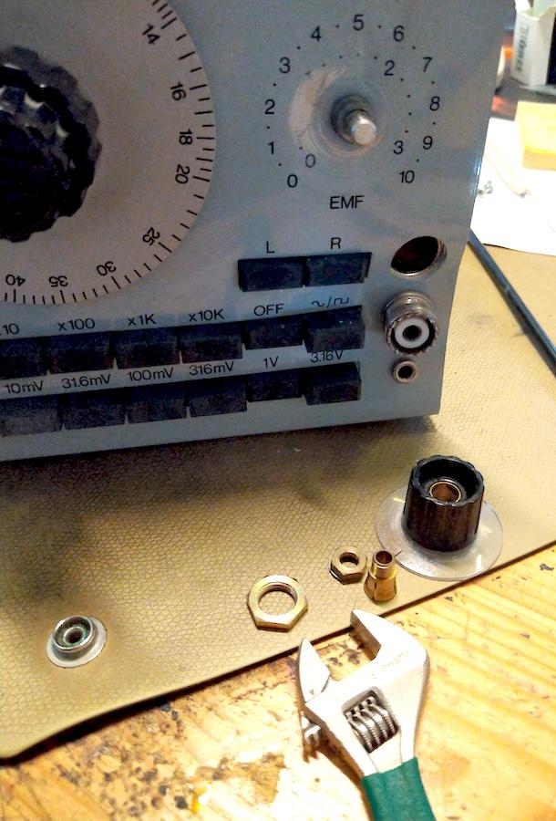
I started taking the front panel out by first removing the knobs:
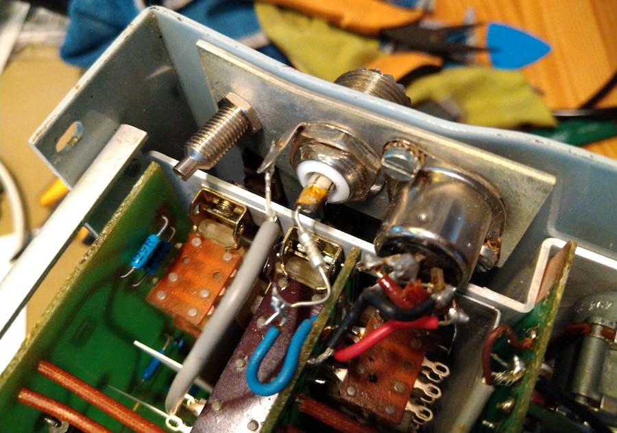
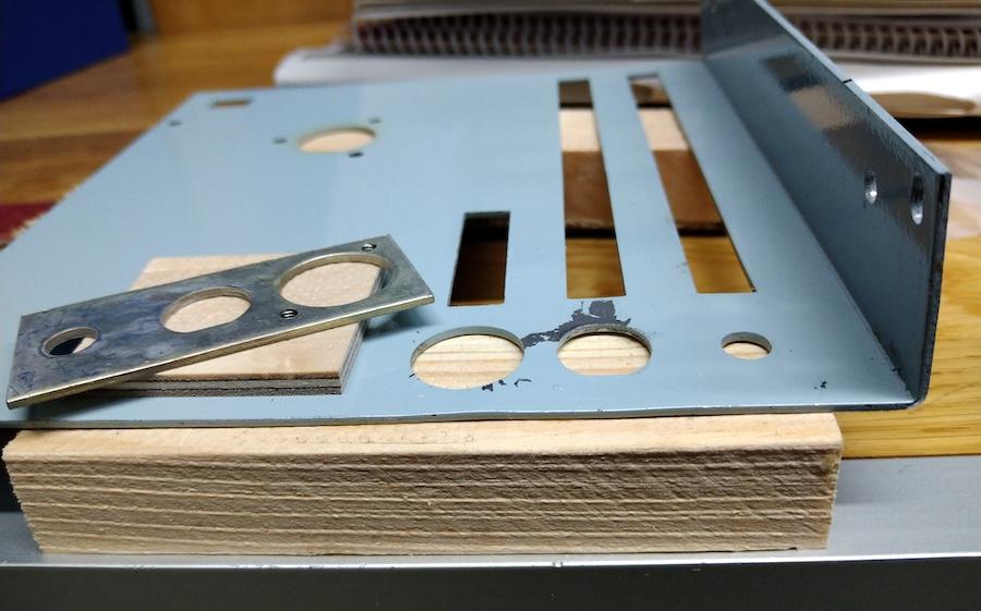
The output connectors have a small metal plate on the back:
The connectors themselves look absolutely fine, that big coax connector looks like it took no damage from the impact.
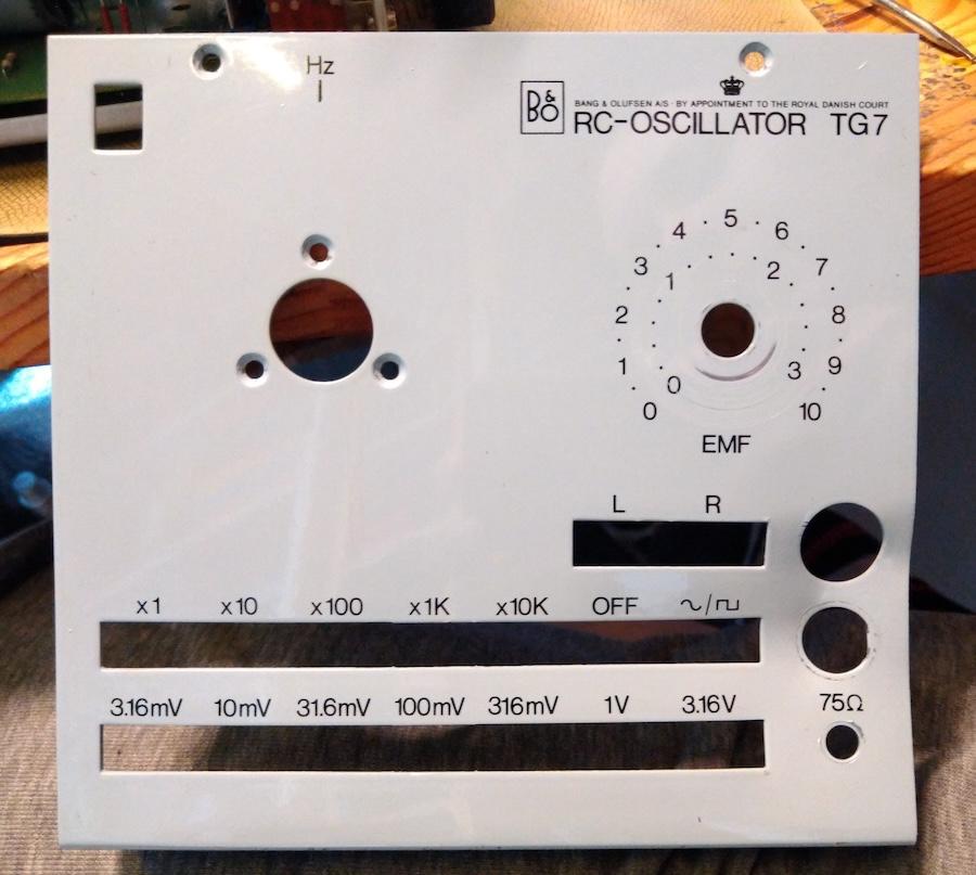
Once removed, the impact area can be seen clearly on the front panel:
One of the bottom feet:
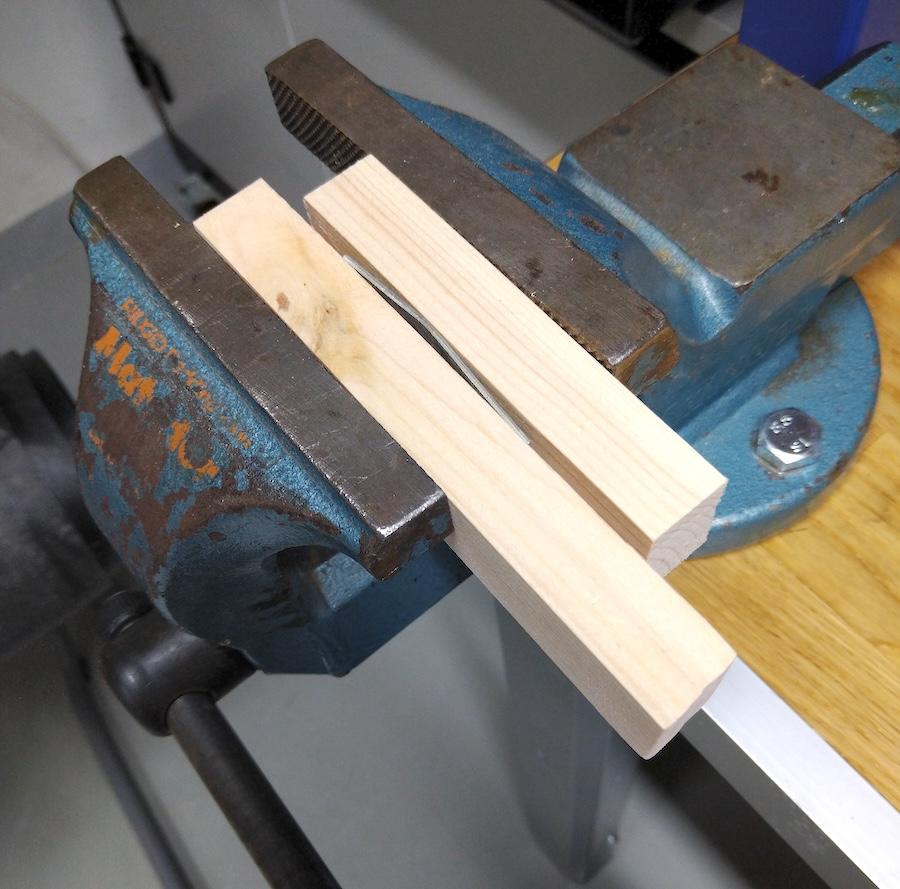
Using a vise I started bending the parts back into shape:
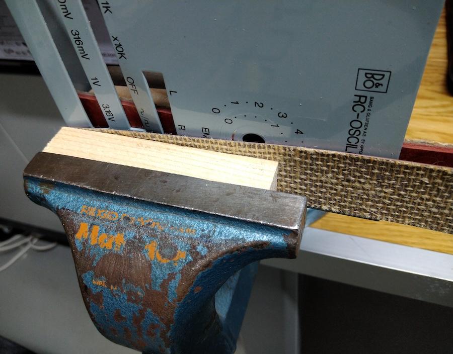
Attempt to cover the front panel for scratches:
And it worked pretty well! In hindsight I probably should’ve attempted to bent it even more (also check if the front-lip is actually perpendicular) as it’s still not perfect, but still it does look a lot better.
Small chips of paint did come off (some was already missing), around the connector holes:
The two right-most output level switches (bottom row) are still not perfectly free to move so I’ll need to do some more work on that.
At least the bend is not so obvious any more!
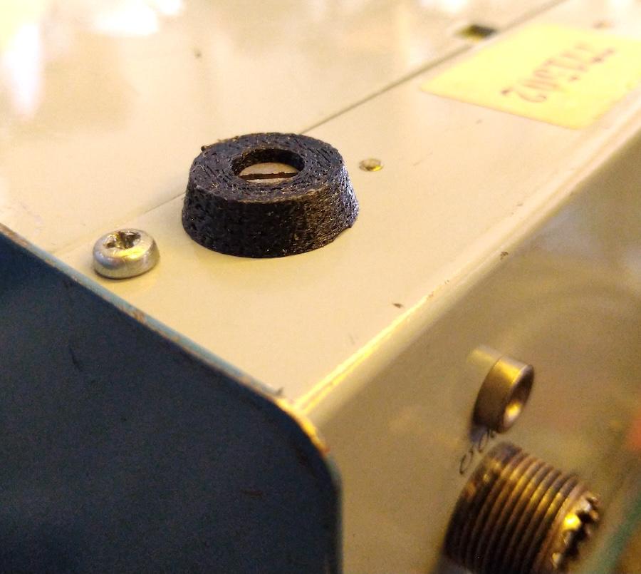
I modeled and 3D-printed a new cap for the knob, and some new feet:
I made first test-batch with PLA, but I did the final print with TPU which is a bit rubber-like flexible filament:
Might not look as pretty as real rubber, but works well for the feet. I soaked the orignal screws in vinegar and they cleaned so well that they were re-used and I needed to source just one more screw for the missing feet.
The issue with the frequency dial was traced to a presumably earlier repair attempt; the linkage between the dial and the variable capacitor goes between some gears and at one point there is a mechanical stops to prevent it from over-turning the variable capacitor, it was just put in at a wrong position. Taking it apart, cleaning and relubing and re-insterting it in another position and now the dial goes a complete revolution with the scale.
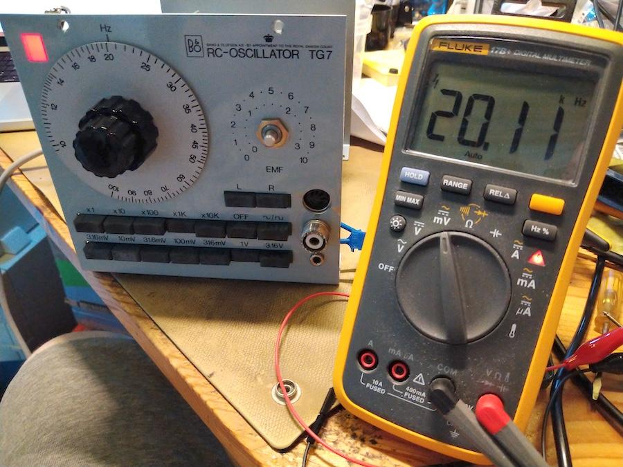
Using just a multimeter (with a non-precision frequency measurement function) I coarse-fitted the dial back into place, I’ll need to calibrate this later.
I’ve had a quick look with an oscilloscope and I’ll use that to make the final adjustment. The waveform seems stable even on the highest ranges, both sine and square waveform. There is a small issue with the x10 range as the waveform is clipping on the bottom. A bit stranger fault is that the output signal level seems way higher than set with the push-buttons; this might have something to due with the range selector buttons if those are still not latching correctly.
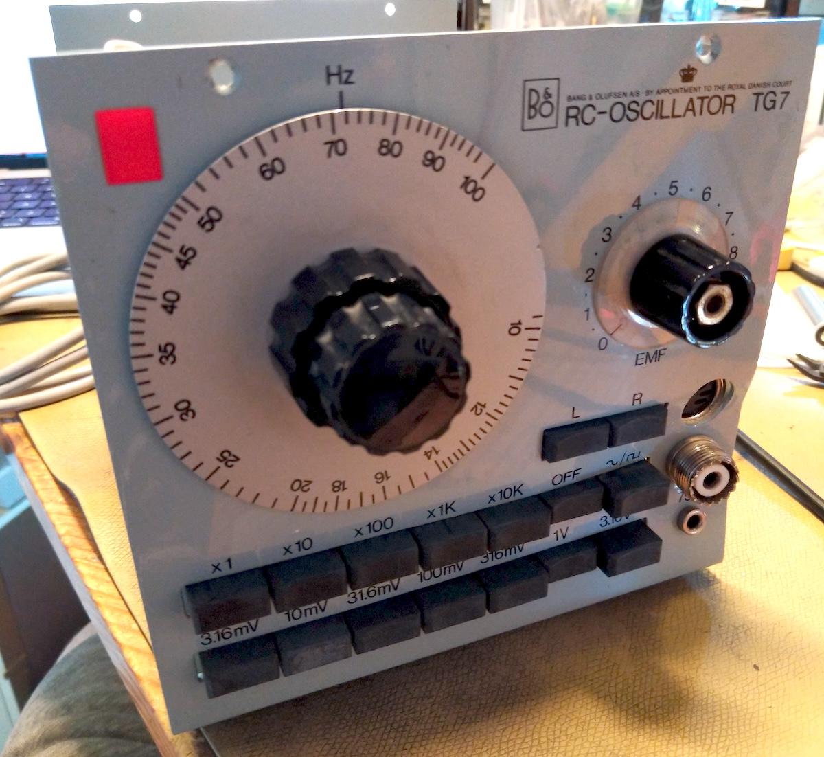
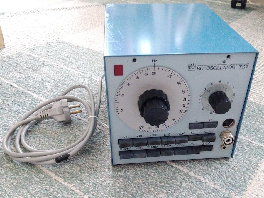
Some work still ahead, but it’s basically working and starting to look quite presentable now:
Thanks for reading!
Location: Helsinki - Finland
My B&O Icons:
3 August 2024 at 18:58 #57973Madskp
GOLD MemberNice writeup. There is something about those blue B&O instruments. You can almost feel the quality of them.
I had a student job in the drawing archive in the R&D department of B&O for a year back in 1996/1997. Those blue instruments were all over the place in the R&D department back then.
I have a SN14 power supply myself that I have had for almost 30 years now and had much use of. It might need some servicing by now though as the voltage regulation is a little unstable now.
I also have this box with a disassembled TG7 and an extra main PCB that I got from my father. He has no idea what might be wrong with it, and its not high on my priority list. But maybe someday 😀
Location: Denmark
4 August 2024 at 13:49 #57988 BRONZE Member
@Madskp: thanks, and a nice story! I can’t find the thread now, but in one of the Beogram 4000c demonstration videos there was a clip presumably from a B&O lab with a whole bench of these original blue-case instruments still in use, that was neat.
It’s neat that B&O made these and even made the design effort to where these really work nicely together in a bench setup.
Hopefully you’ll assemble that TG7 some day and it’ll work 🙂
I presume the case feet are identical between power supplies and multimeters so I put the STL file out there if somebody else needs to print one: https://www.thingiverse.com/thing:6719913.
Location: Helsinki - Finland
My B&O Icons:
-
AuthorPosts
- You must be logged in to reply to this topic.


