Home › Forums › BeoWorld around the world! › Nordic › Beosystem 2500 cassette tape drive.
- This topic has 0 replies, 1 voice, and was last updated 2 years, 10 months ago by
redfox.
-
AuthorPosts
-
16 April 2023 at 09:54 #45845
redfox
BRONZE MemberHello Everyone,
I am away on a long journey in a far away country, so I am not having any tools etc. at hand.
Anyway, I have taken the cassette tape drive out of a Beosystem 2500 to change the belt, which was melted. Looking at the drive, I think there are a few problems, which happened one year ago, when I was last here, when the cassette tape drive said “crash”.
So:
1/ there are two springs for the left side rubber pressure roller. And it flips back with spring pressure if I move it slightly upwards.
On the right hand side, there is only 1 spring installed. And there is no spring loaded return movement, if I touch it slightly. So, one can say it moves freely for now.
Looking at the mildly bad service manual, which had quite limited instrucvtions and drawings, I think I can see that indeed there would be 2 springs for the left side and only 1 spring for the right hand side rubber pressure roller.
Is that correct?
And if so, does that mean, that if the system is complete and powered on, upon inserting a cassette tape, and play, and reverse direction, would that mean that there is a mechanism in this drive that spring loads the right hand side? If now, what functions does it have then? I do think there must be some sort of movement of a spring function, otherwise I don’t think the right pressure roller would work.
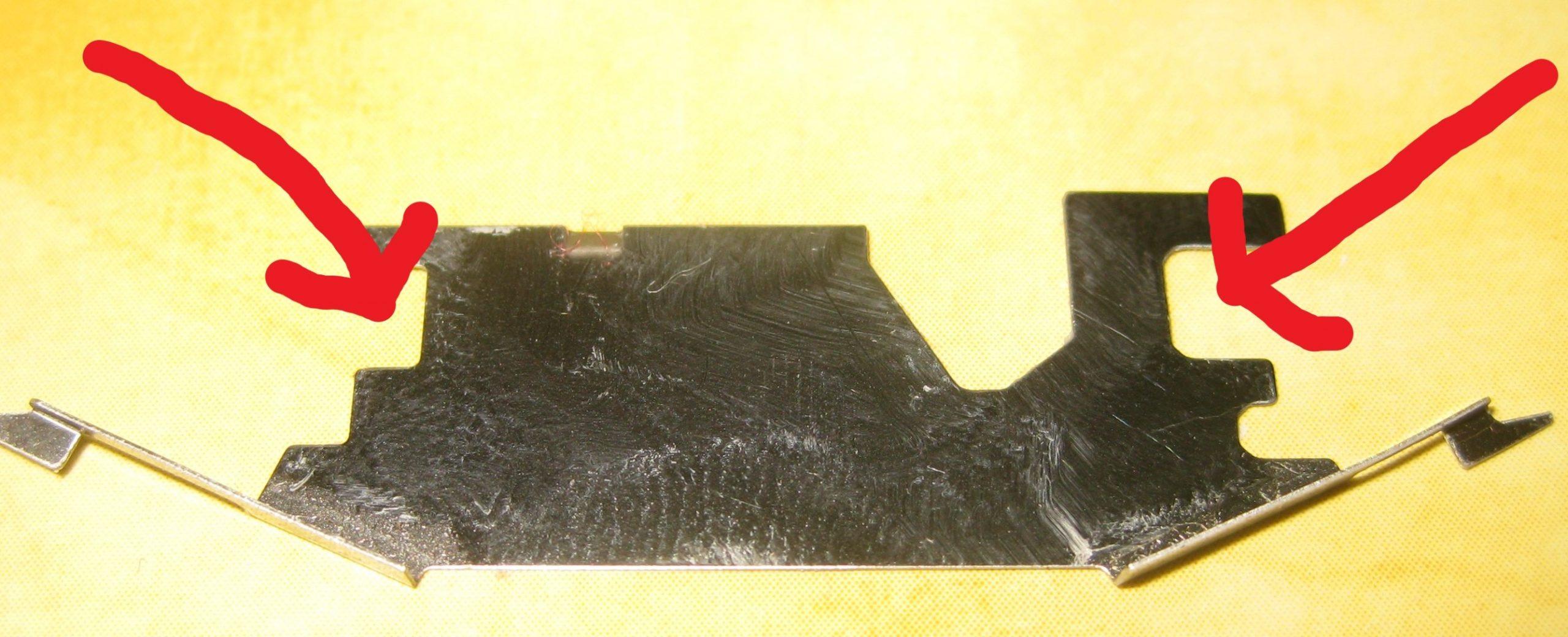
2/ Just above the head bridge, is a mirror polished very thin pieve of flat metal with 2 thin arms, one each side. I think it is called “part 9435, spring, tape head assembly”.
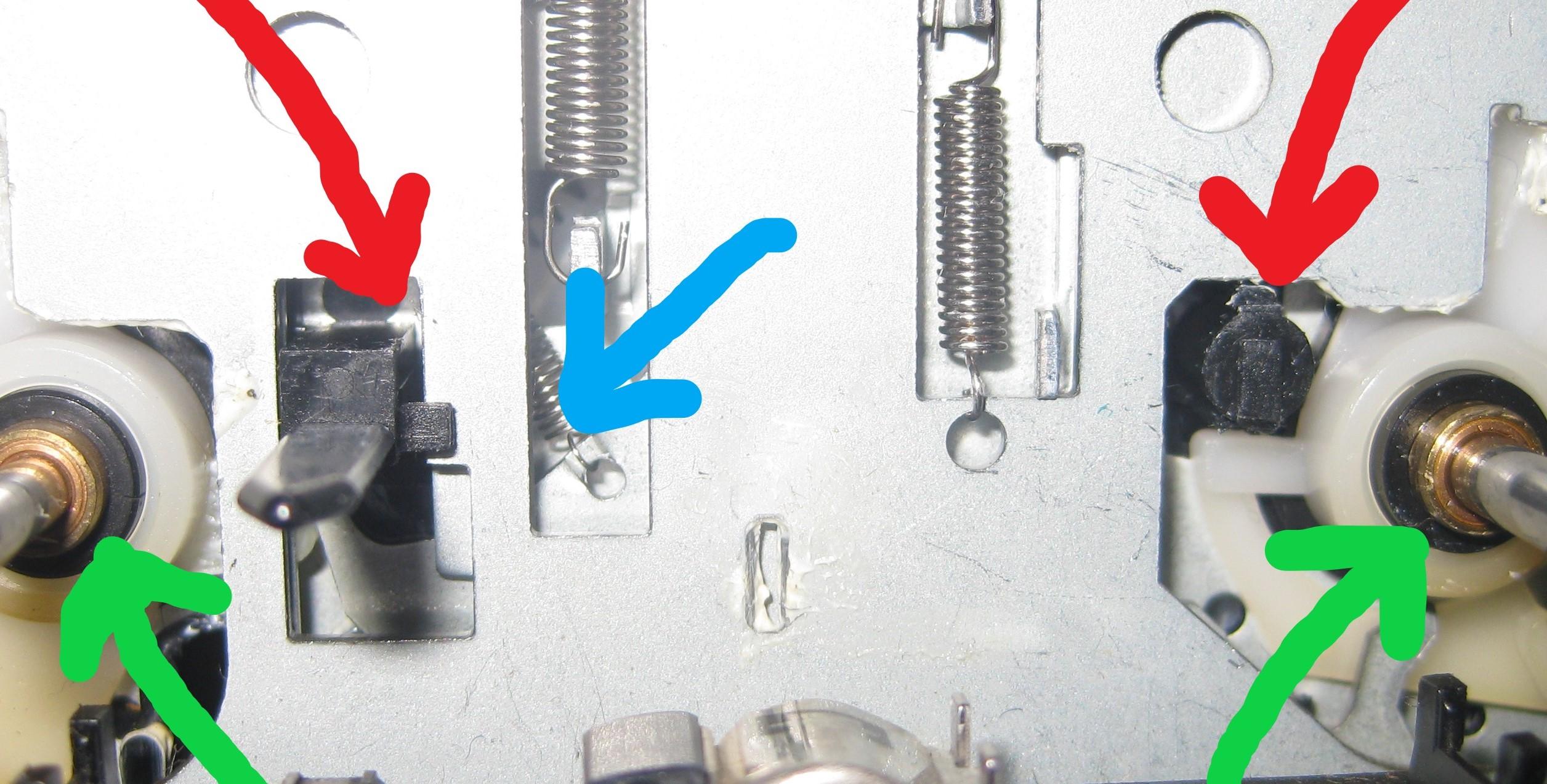
That was loose from when the original “crash” of the tape drive happened one year ago. So, I realise what way it should turn and what side is up. But what I don’t see, is how it is held in position. I have madea picture 1 and 2, which on the picture with the mirror polished part, I have made 2 arrows that pointo to an indentation which must be the one each side, that holds on to some black plastic at the drive, right next to the capstan axles.
On the other picture, of the drive, I have made some arrows that should correspond to the indentations on the metal part (spring). I think there may be a very little very hard to see edge on each of the two black plastic parts (like squares) that the metal part could slide in under and be fixed. On the spring itself, on ht upper edge, is also a very small bent tap, that could sit into the left side slide spring hole in the metal base – also arrowed.
Is that correct?
And how to insert it, as I have tried many times, and haven’t found the way to do it?
On the picture, red arrows points to possible indentation points? Green arrows points tp where the thin ends of the mirrir polished metal part should possibly spring load on the capstan shafts. And blue arrow is where I think the mini bent tap should fix into holding position where a spring is vertically mounted.
I hope you can help out, so I can get on with the belt installation and reassemble the drive and make the nice Beosystem 2500 work properly again.
Please see pics.
Kind regards,
Redfox.
-
AuthorPosts
- You must be logged in to reply to this topic.


