Generic selectors
Exact matches only
Search in title
Search in content
Post Type Selectors

Home Forums Product Discussion & Questions BeoMaster Beomaster 4000 – extra components not documented

Viewing 2 posts - 1 through 2 (of 2 total)
  • Author
    Posts
  • #69906
    Mogens Ranneries
    BRONZE Member

    Hi Forum. I am recapping another Beomaster 4000, but this version has 2 extra trimmers in the output stage, and I cannot find any documentation stating how to adjust them. It seems that they may effect the center/symmetri voltage of the output stage. See attached picture, which I scanned from the in-lay schematics. Unfortunately is does not say anything about adjustments. The extra trimmers are position 585 and 586 (right channel).

    Anyone who has seen this version and knows the adjustment procedure?

    #69939
    Dillen
    Moderator

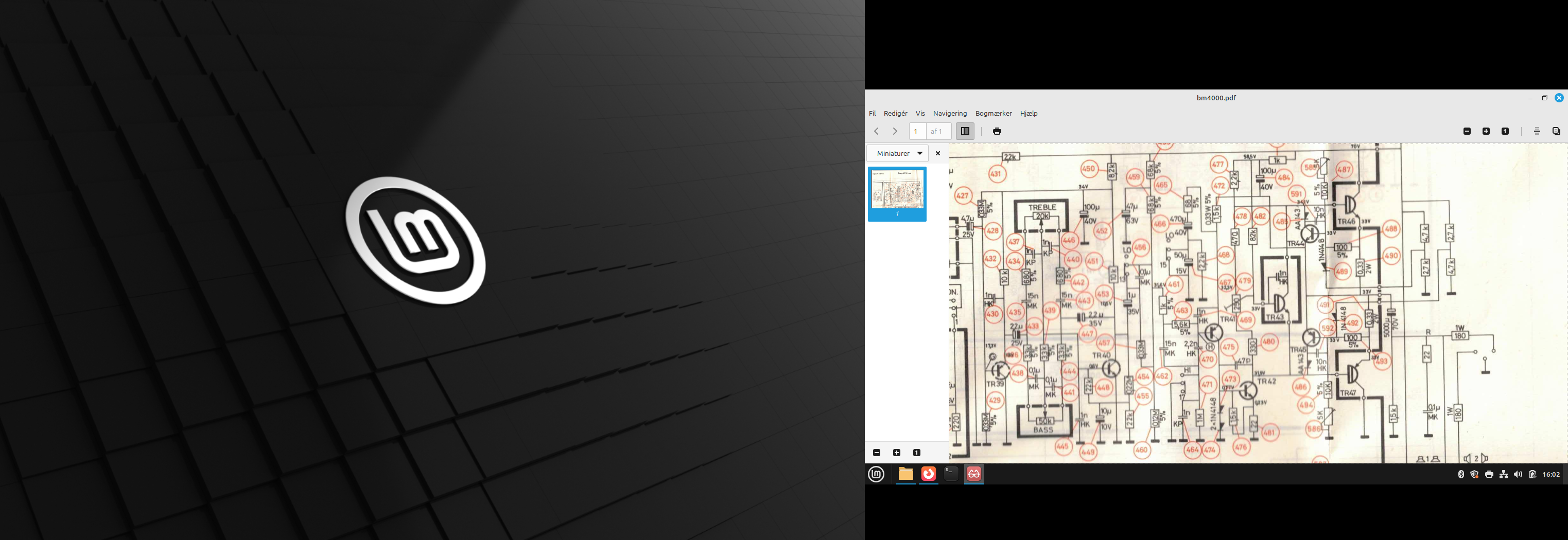
    Adjustment of potentiometer pos. 585 and 586

    Connect oscilloscope to the speaker output

    Amplifier is fed 1 kHz sine, until clipping starts

    Capacitor 4.7uF is mounted across C-E of TR43

    Resistor 190ohm 23Wa (part# 5107005) is mounted across C-E of TR46

    Potentiometer 5Kohm pos 585 is adjusted until distortion on negative peak

    Resistor is moved to C-E of TR47

    Potentiometer 5Kohm pos 586 is adjusted until distortion on positive peak

    Left channel is adjusted as above

    Martin

Viewing 2 posts - 1 through 2 (of 2 total)
  • You must be logged in to reply to this topic.