


Home › Forums › Product Discussion & Questions › BeoMaster › Beomaster 3000-2 Type 2402 15V Power Supply Not Activating
Tagged: 3000-2 15V power supply
- This topic has 42 replies, 2 voices, and was last updated 2 months ago by
 Johnny Law.
-
AuthorPosts
-
14 December 2025 at 16:05 #71922
 Johnny LawBRONZE Member
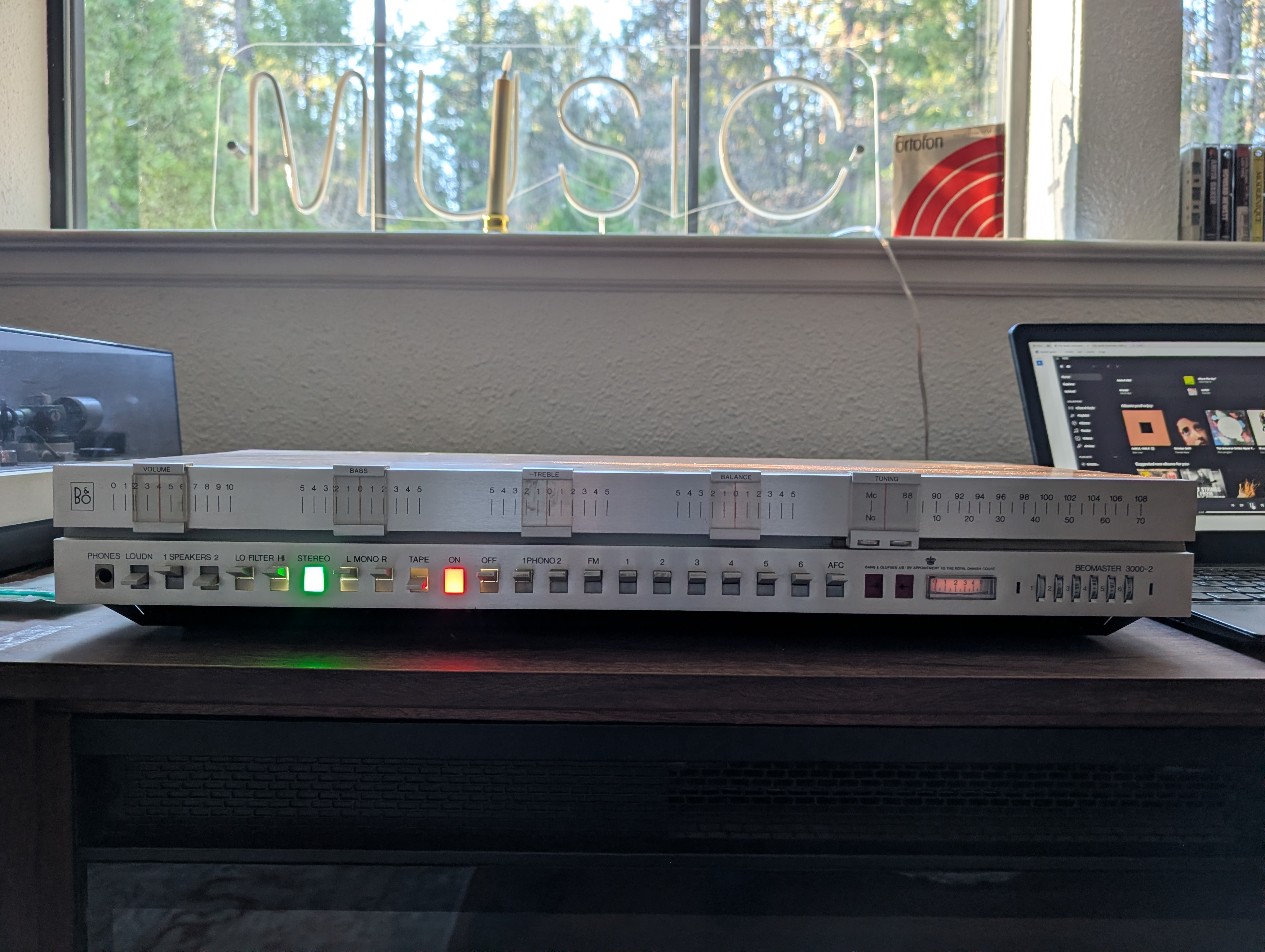
I still need to address a few things yet – mainly about the tuner, it has horrible reception and the tuning range is way off (it stops at 105MHz instead of 108MHz …) – I may start a new thread – but the amplifier itself works wonderfully now!
I dialed in the idle current to ~100mA …
 Set up with my S45-2 speakers and playing its first music in decades …
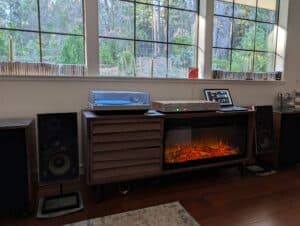
 Cheers!15 December 2025 at 10:31 #71940hcraig244SILVER Member
Also bear in mind that some components can measure up fine when tested, but fail under load…..I’ve had this issue in the past, and replacement parts from suspect suppliers should be avoided…early transistors can still be found as old stock and are a safer bet than ebay
Craig
hehe…..
15 December 2025 at 10:37 #71941hcraig244SILVER Memberdid you change the tuning indicator lamps in the tuning circuit? if so these must be replaced by lamps of the exact current pull….i had an issue with some i changed on a 4400, Dillen provided the correct lamps and all was well.
Craig
16 December 2025 at 03:13 #71965Johnny LawBRONZE MemberCraig – Yeah, nailed it!
All of the original bulbs had burnt out – aside from the tuning meter bulb – so I am using LEDs.
.. I had read about the tuner needing 12V / 0.03A discriminator bulbs … in some past thread I read. I guess that was true 🙂 So I’ll find some.
In the meantime, I’ve done a good job making a mess out of things.
Streaming audio was sounding good via the Tape input, so then I tried Q1 with my record player … but I wasn’t getting any sound out of the left channel. My first thought, since I wasn’t at my bench, was to try adjusting the level controls underneath … and in doing so, the R channel potentiometer decided to be frozen and then to tear apart completely (the part that spins along the lower metal path tore off the base).
So I took it back out to the bench to assess the damage. I removed both channels’ pots (the good L one and bad R one) and thought I could use resistors to effectively simulate a fixed pot. I used two pairs of 15kohm & 40kohm resistors (closest to 50k total as I have on hand).
I also pulled and tested all transistors in Q1 pre-amp, and all were fine. In doing so I found a broken PCB trace in the L channel – which explains the lack of sound before.
Put it all back together and now…
- No sound at all from either Q1 channel
- Sound with all other inputs is now distorted through speakers, namely bass / lower frequencies. Almost like it’s clipping. Imagine how a bass note would sound through a household fan – like if Darth Vader were speaking all the bass notes.
So … neither of those things were either expected nor are they Good Things to Happen.
I have no idea why either of those things are happening, I suppose it won’t be until the weekend that I can begin to investigate.
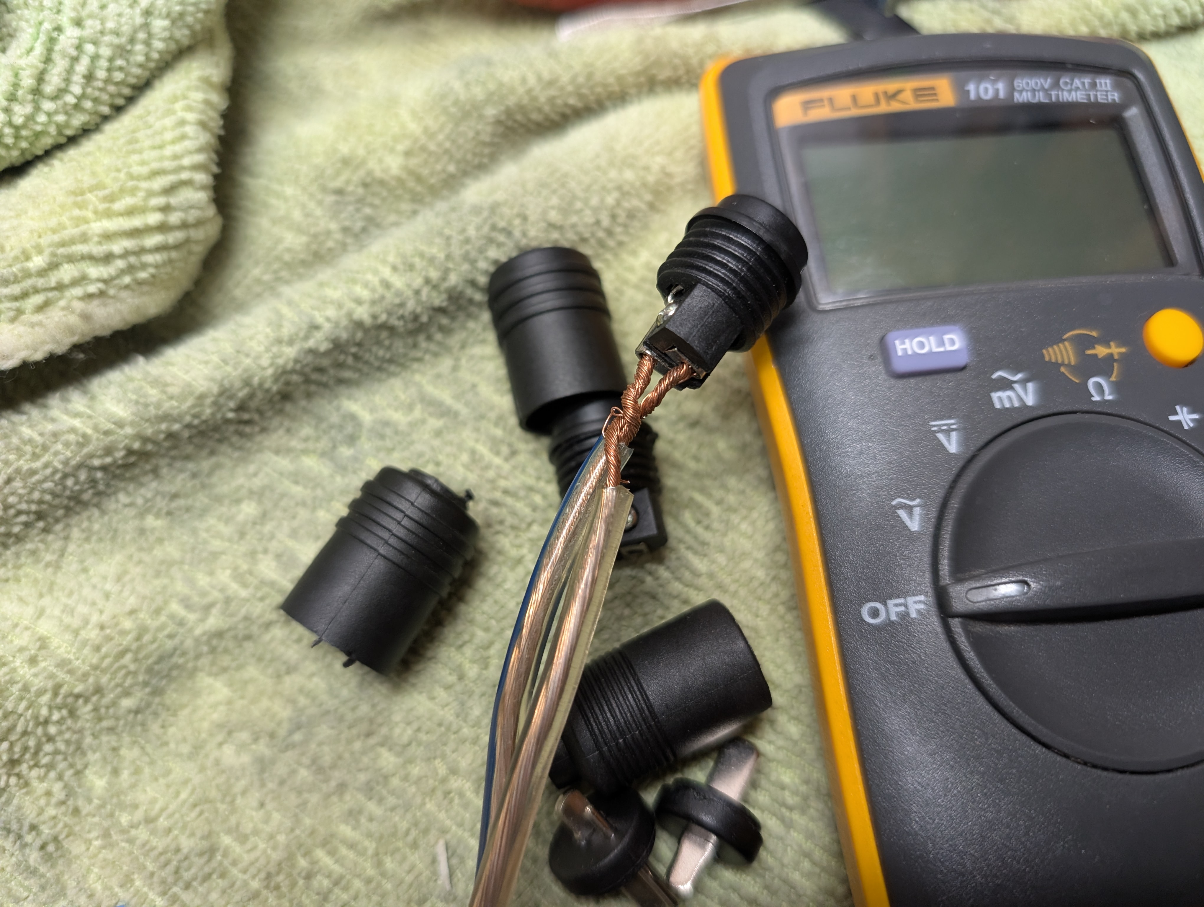
21 December 2025 at 21:39 #72053Johnny LawBRONZE MemberFirst discovery: a gift from 10-years-ago-me. (When I first acquired my 3000-2 and, I put these DIN plugs on a pair of speaker cables … but obviously didn’t think they might get twisted.) 10 year-younger me, what an idiot!
So … I guess I was playing this thing with shorted speaker cables … d’oh …
Then I discovered that listening (Tape input) via headphones has no distortion. But through speakers, distortion.
So I thought – a-ha, must be a problem with the speakers (aka I hope it’s the speakers and not the amp…).
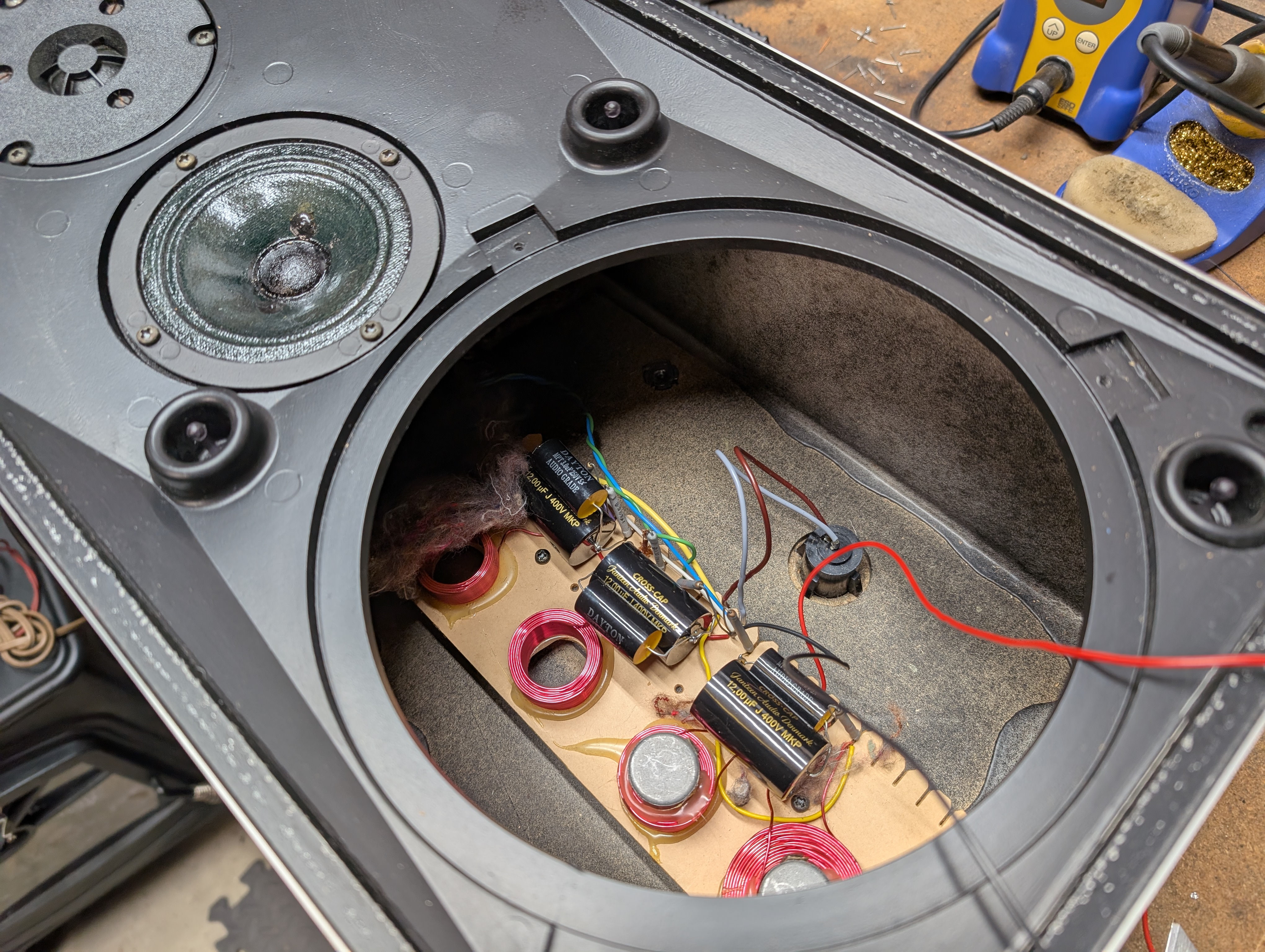
As it turned out, I happened to have the right caps on hand thanks to an aborted re-cap project for another pair of speakers a few years ago.
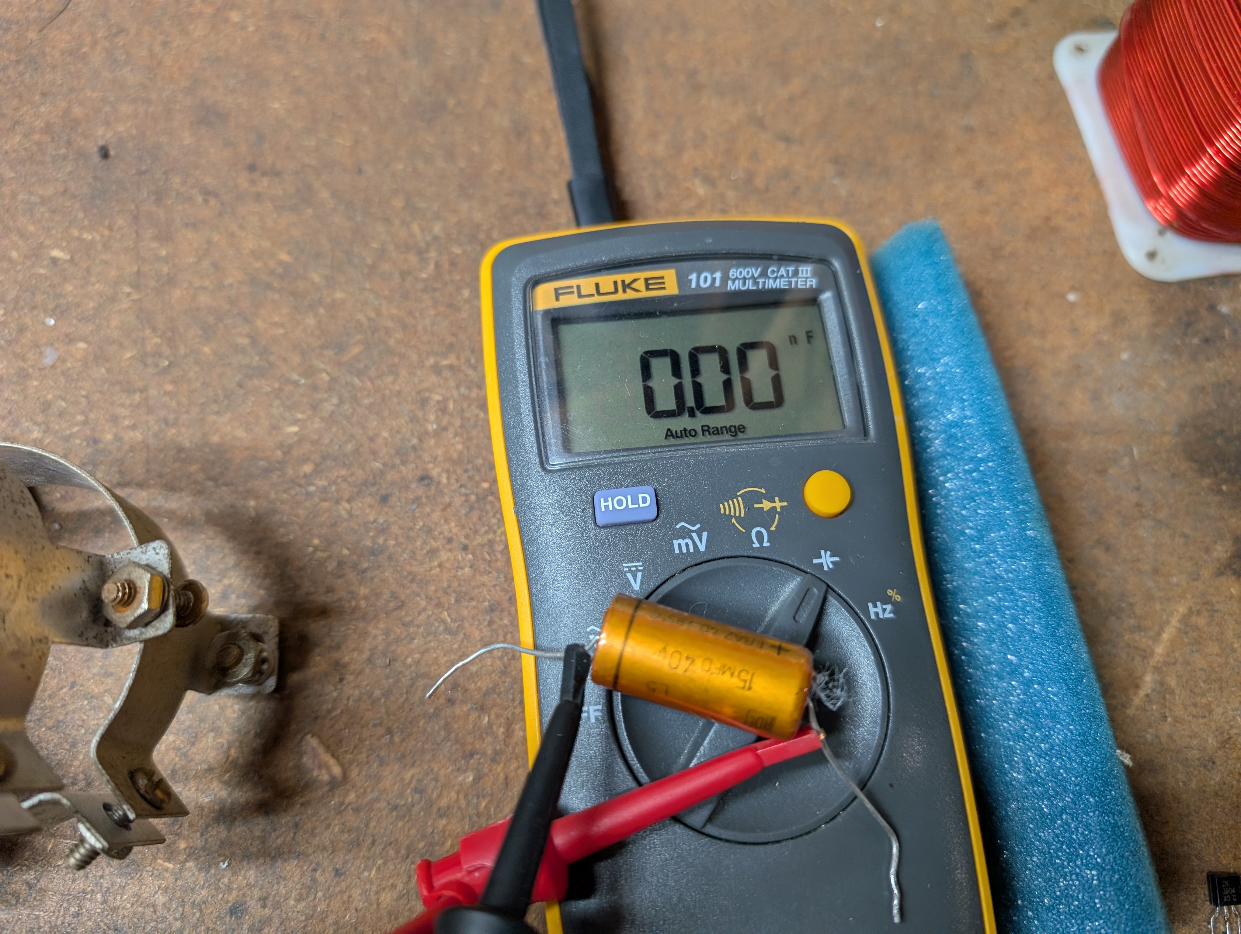
This led me down a side quest … re-capping my S45-2 speakers. Of the 6 15uF caps in the two speakers, 5 of them measured ~18uF and 1 of them measured 0uF.
The drivers and resistors measured fine … so back together the speakers went.
I also made new cables WITHOUT shorting anything … and put it all back together.Through headphones, no distortion. But as soon as I click the Speakers switch, it becomes distorted, even through the headphones, on both channels.I swapped speaker cables left to right, swapped my input left to right, and narrowed it down to distortion – only through speakers, not headphones – on the Right channel only.So now, to try to figure out what’s causing the distortion in the Right channel via Speakers but not Headphones.22 December 2025 at 12:50 #72058hcraig244SILVER MemberThis is where a signal generator and oscilloscope come in real useful, you can track the signal path through the circuit until you pick up the distortion…….not much help I know 😳
6 January 2026 at 18:08 #72383Johnny LawBRONZE MemberA combination of my stupid mistakes and the ethereal nature of all physical objects thanks to the constant and relentless erosion of the universe as we and everything we touch slowly degrades into an entropic eternity … just another Tuesday.
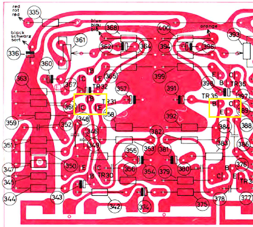
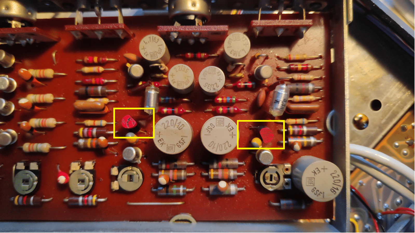
Q1 didn’t work because – surprise (to me) – the pin orientation on the PCB of TR31 and TR35 are cock-eyed relative to the package. In other words, instead of going straight into their emitter / base / collector holes – like every other transistor in this thing – they go in sideways. And also, there’s an error in the service manual. TR35’s E and B are switched! So don’t install TR35 as shown.
I.e., they are supposed to look like this (in the yellow boxes):
… and I had put mine back like this WOOPS
6 January 2026 at 18:17 #72386Johnny LawBRONZE MemberThen, about that distortion … found a smoking gun, R481 decided to break, screwing up the right channel’s idle current and causing the distortion.
Soldered it back together and we’re back in business w/out distortion.
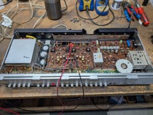
I did notice that one emitter resistor is reading low idle voltage drop compared to the other one (settled on putting it at 10mV with the other one at 14mV). I don’t have any equipment sensitive enough to measure 0.15ohms so I wasn’t able to confirm whether or not it has drifted … so I just hooked it up, set idle current according to the manual and it’s back in action (again) and sounding great via Q1 (my record player) and Q2 / Tape (my CD player).The FM issue remains … the tuner range maxes out at 105kHz now, I get static when the stereo light is on, etc. Digging into that next …7 January 2026 at 17:57 #72412hcraig244SILVER MemberProgress…..I have also found a number of instances where the circuit diagram has been in error….I always take pictures of the units I work on before disconnecting or replacing items, I have also found instances where the actual markings on the PCB have been wrong.
You should replace all of those skeleton trimmers as soon as possible…if they let go you can blow your output transistors…and after all these years they are quite fragile…encapsulated trimmers are easy to obtain…a good idea would have been the purchase of a kit from dillen which contains all the recommended replacement components ;¬)
Craig
14 January 2026 at 18:08 #72547Johnny LawBRONZE MemberThe first FM problem: the tuner has lost the 88 – 108 MHz range. It tops out around 105MHz on the top end and around 89MHz on the low end.
I can fiddle with the local oscillator in the FM front end to shift the range up and down, but it always stops short of receiving the entire public broadcast FM spectrum.
I am wondering if this is a symptom of the inductive coupling between the FM pot and the FM front end’s LO falling apart?
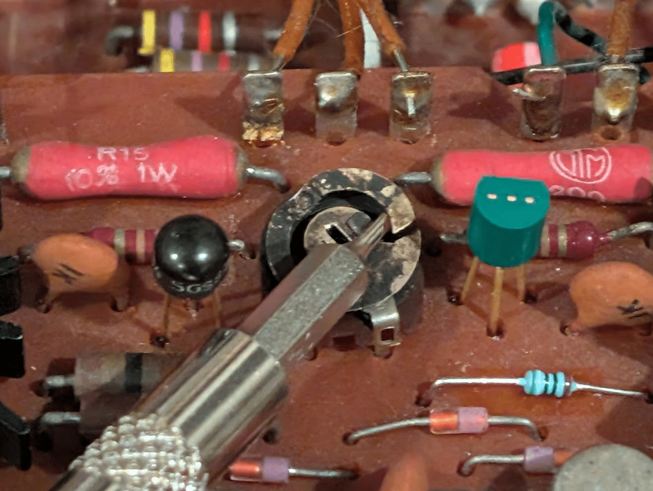
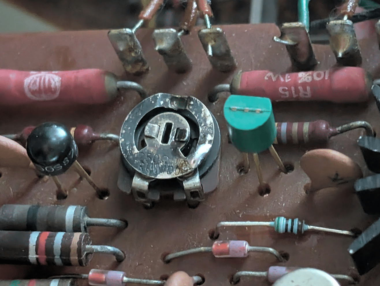
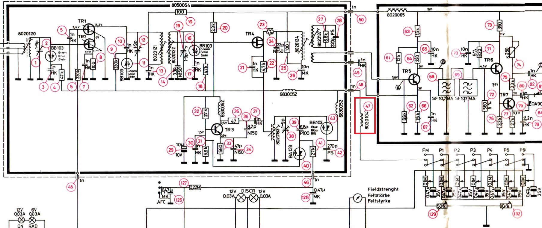
I’m talking about #47 in the schematic, in the red box:
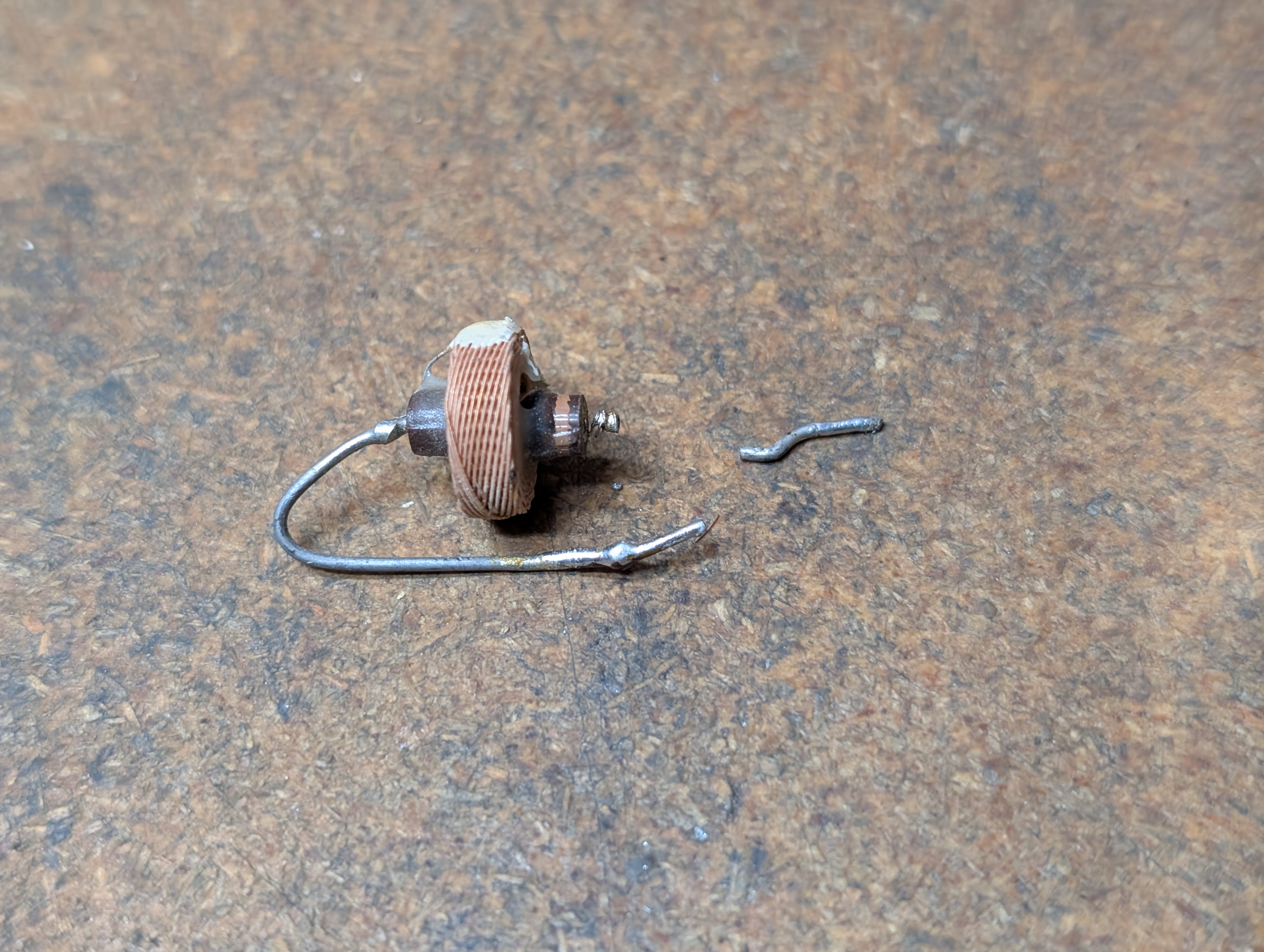
Here’s a pic of what happened … when I went to de-solder it, one of the thick mounting pins came apart. But I am pretty sure that the thick pin is not conductive, but rather it only conducts through the wound inductor wire – which I soldered back onto the pin and put back into place.
It goes here in between the empty loop on the front end and the empty hole next to it on the FM PCB:
I would suspect that if it’s preventing the appropriate voltage from reaching the capacitance diodes in the FM front end, that’s preventing the front end from reaching the ends of the frequency spectrum?However – I don’t measure any voltage loss across it. So it seems to be conducting fine.Does anyone know what voltage I SHOULD be seeing at that connection at 88MHz and at 108MHz? There’s no reference voltages in the schematic so it’s impossible to know if mine are correct or not …14 January 2026 at 18:11 #72548Johnny LawBRONZE MemberI should add, I verified that my 22V power supply is good.
Also, the 6 FM presets are the same … they are limited to the same narrow frequency range as the main FM mode, leading me to believe that 129 and 132 are both OK as well as all of the 0.47uF tants (which are original and have not been measured or replaced). But – I could be wrong.
15 January 2026 at 01:21 #72557Johnny LawBRONZE MemberFor reference, measuring at the FM front-end side of inductor #47 I am seeing the following range of voltages from lowest FM frequency to highest: ~4.3V to ~19.0V. Same for FM and each of the 6 presets.
Is that correct?
15 January 2026 at 09:59 #72559hcraig244SILVER MemberI think I have a 3000-2 floating around somewhere…..i’ll have a look for it and if i find it i will take some measurements for you, you’ll need to be specific which points to measure
Craig
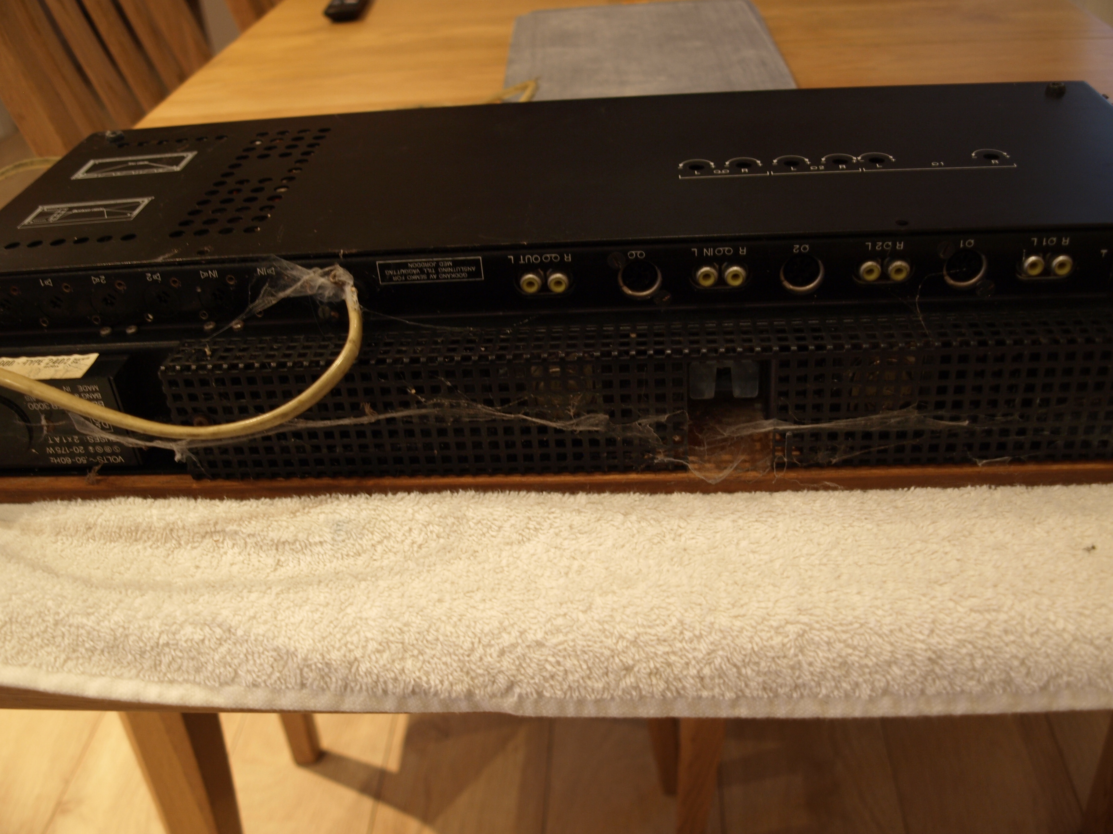
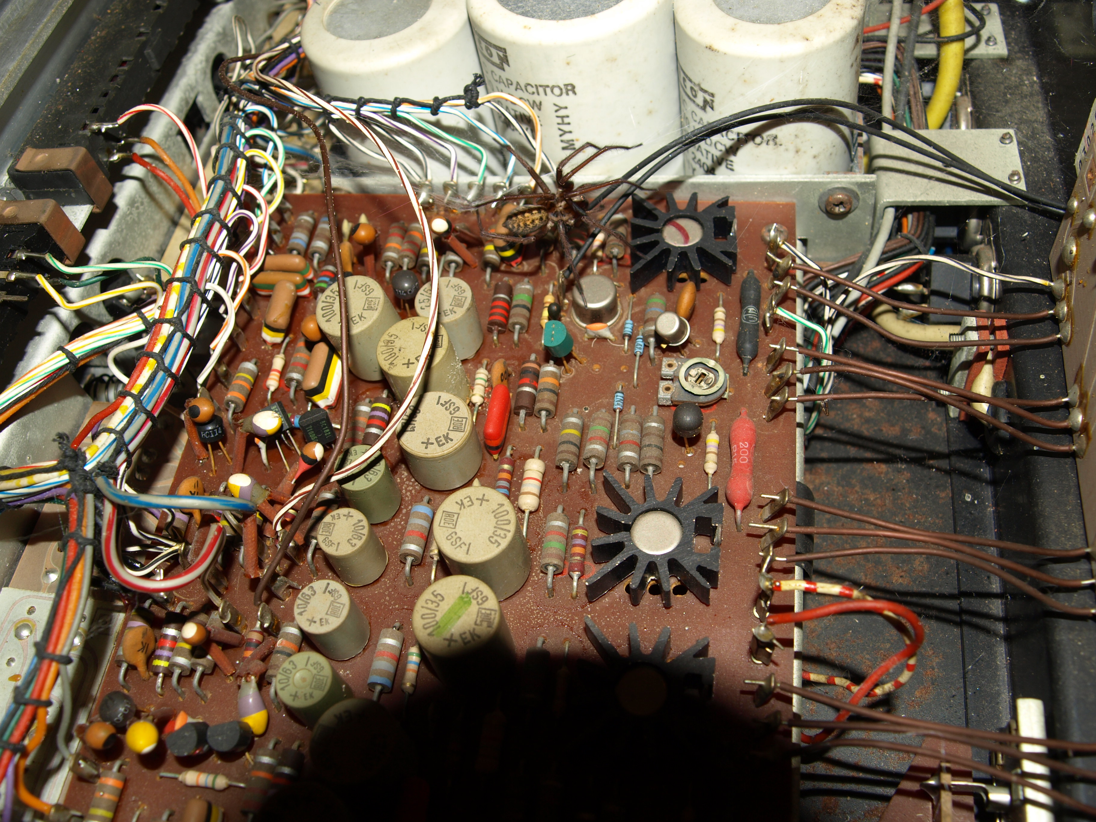
15 January 2026 at 17:57 #72571hcraig244SILVER Memberfound this in the bowels of the workshop, suspected I had one but wasn’t sure…dont even remember acquiring it to be honest!
looks a little sorry for itself…i think I must have bought it several years ago and not got around to it15 January 2026 at 18:13 #72578hcraig244SILVER Memberlooking inside i discovered I was not alone in there…
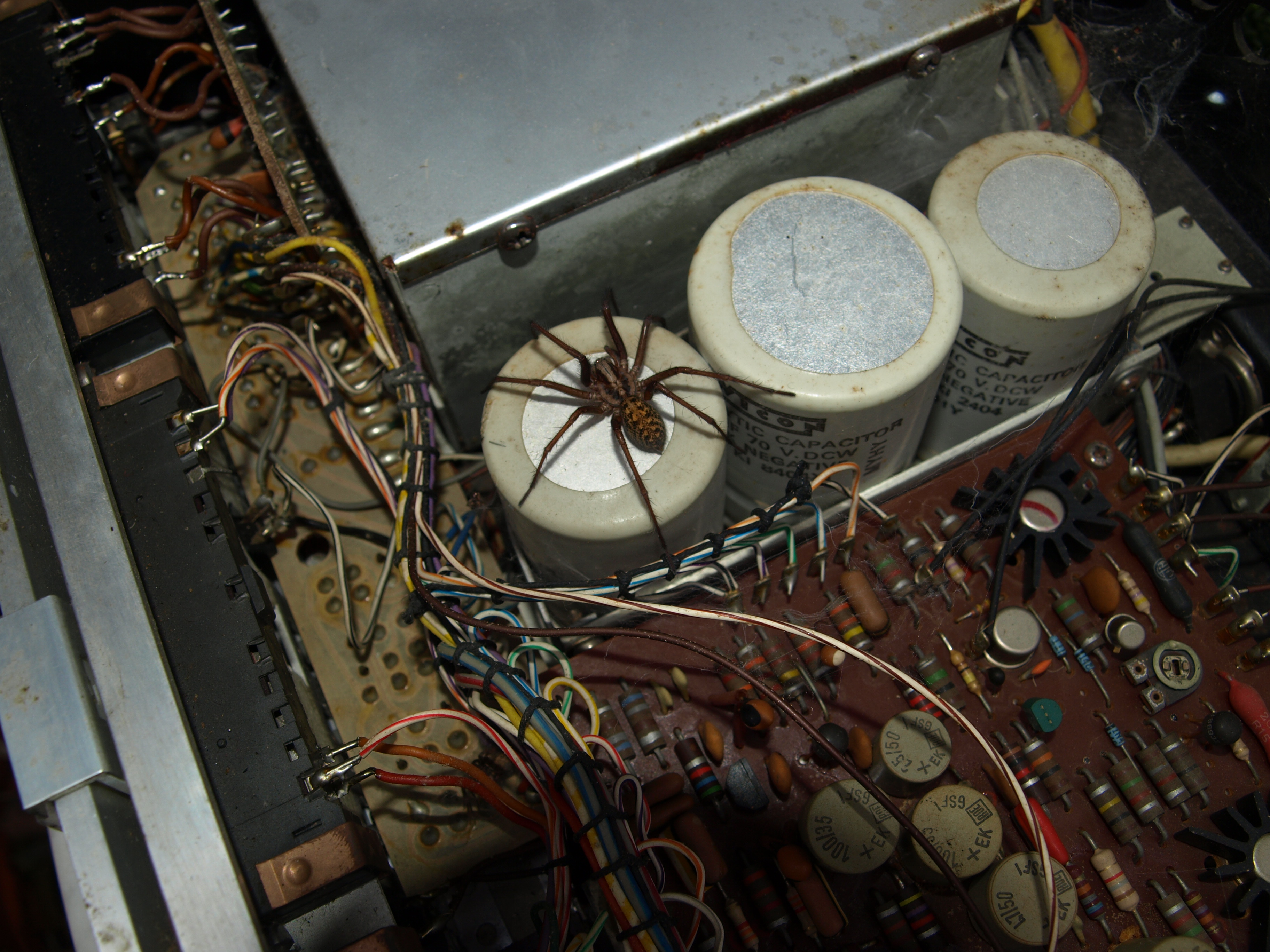
15 January 2026 at 18:14 #72580hcraig244SILVER MemberLook at this bad boy….
15 January 2026 at 18:17 #72581hcraig244SILVER Membertook it outside and let it go….hope it doesn’t come back into the house! will have a bit of a clean in here and make sure it all looks well before powering up…..i suspect it wont come to life or I wouldn’t have acquired it.
15 January 2026 at 18:48 #72582Johnny LawBRONZE Member(Just kidding – I take spiders outside and let em go too!)
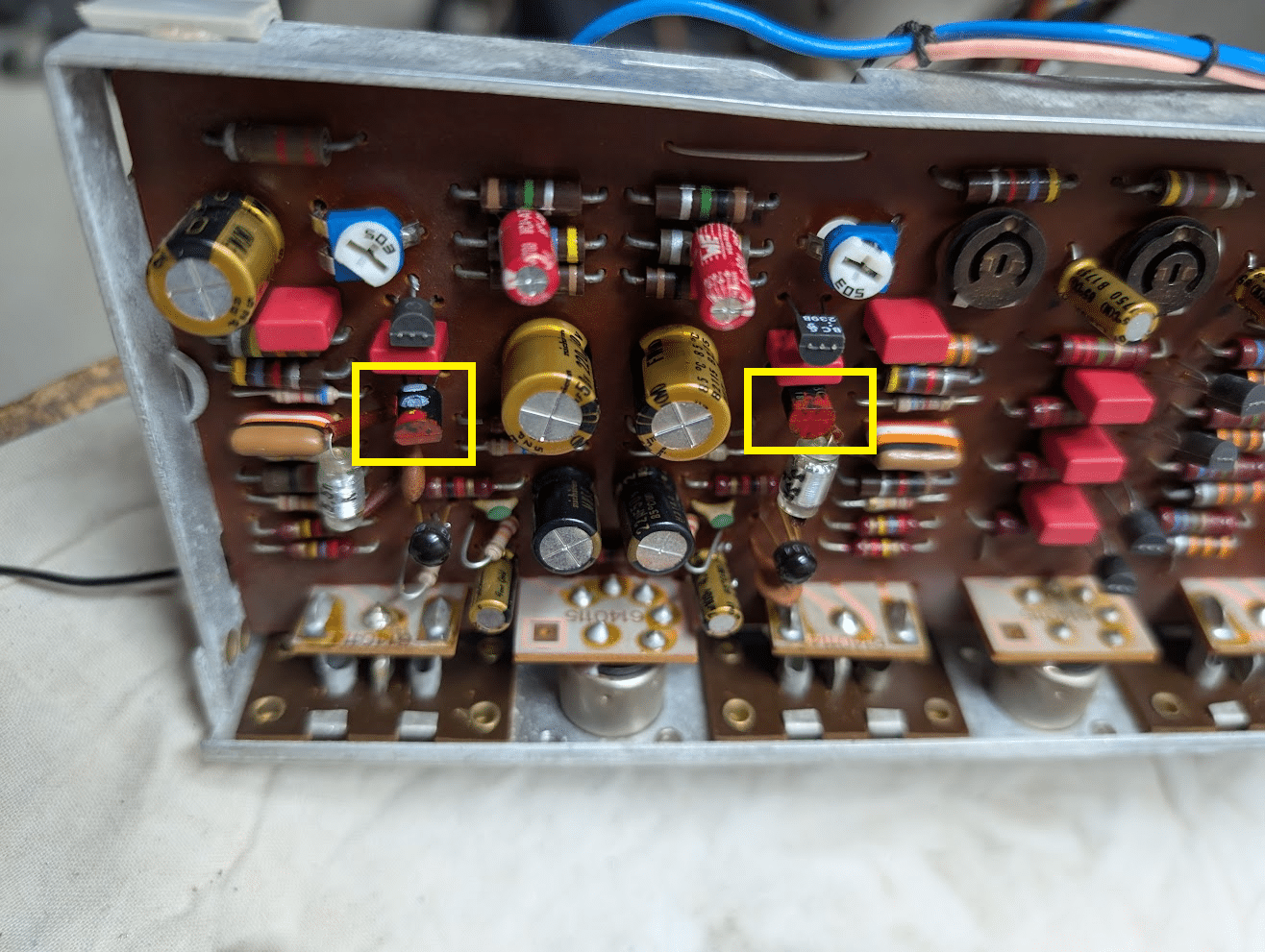
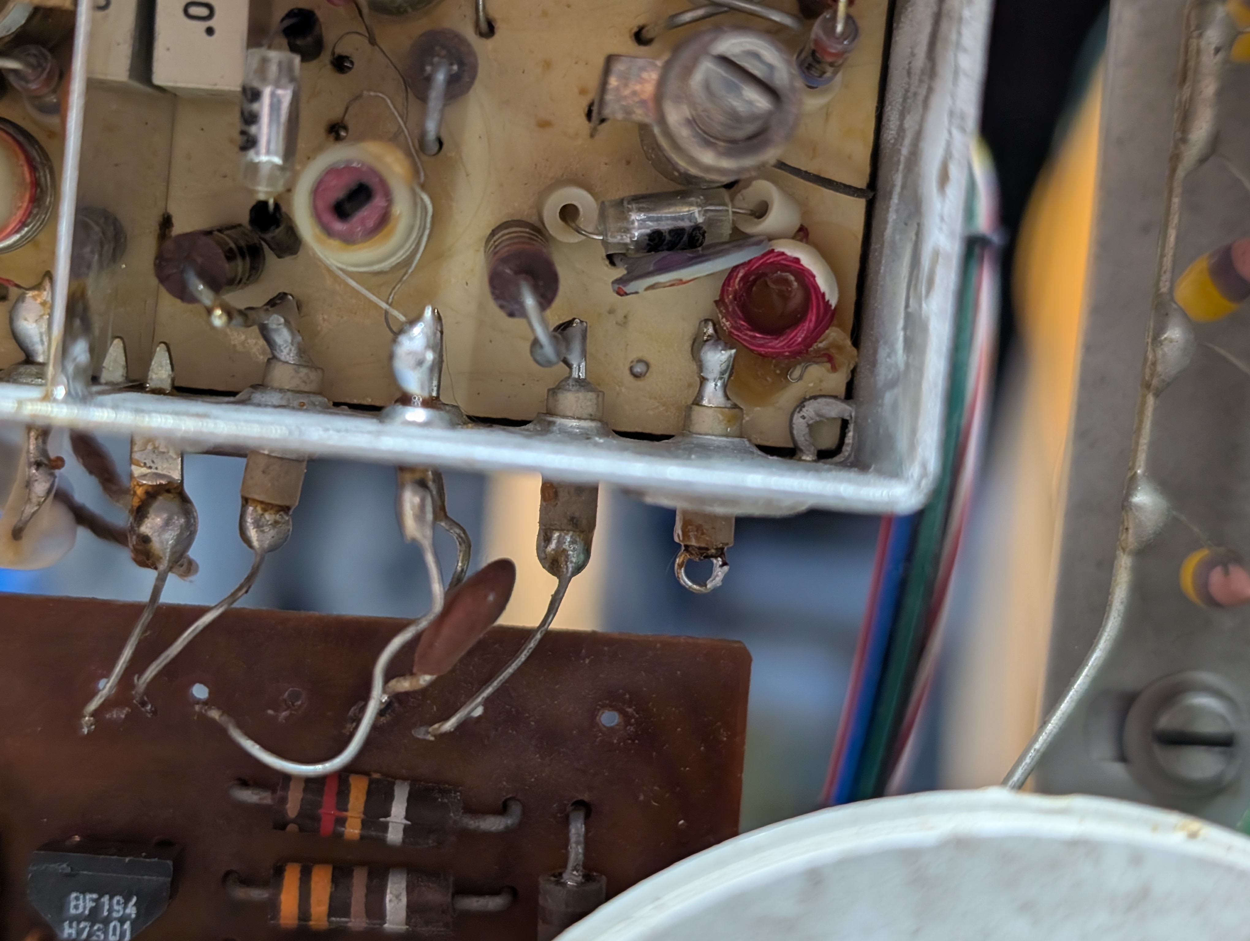
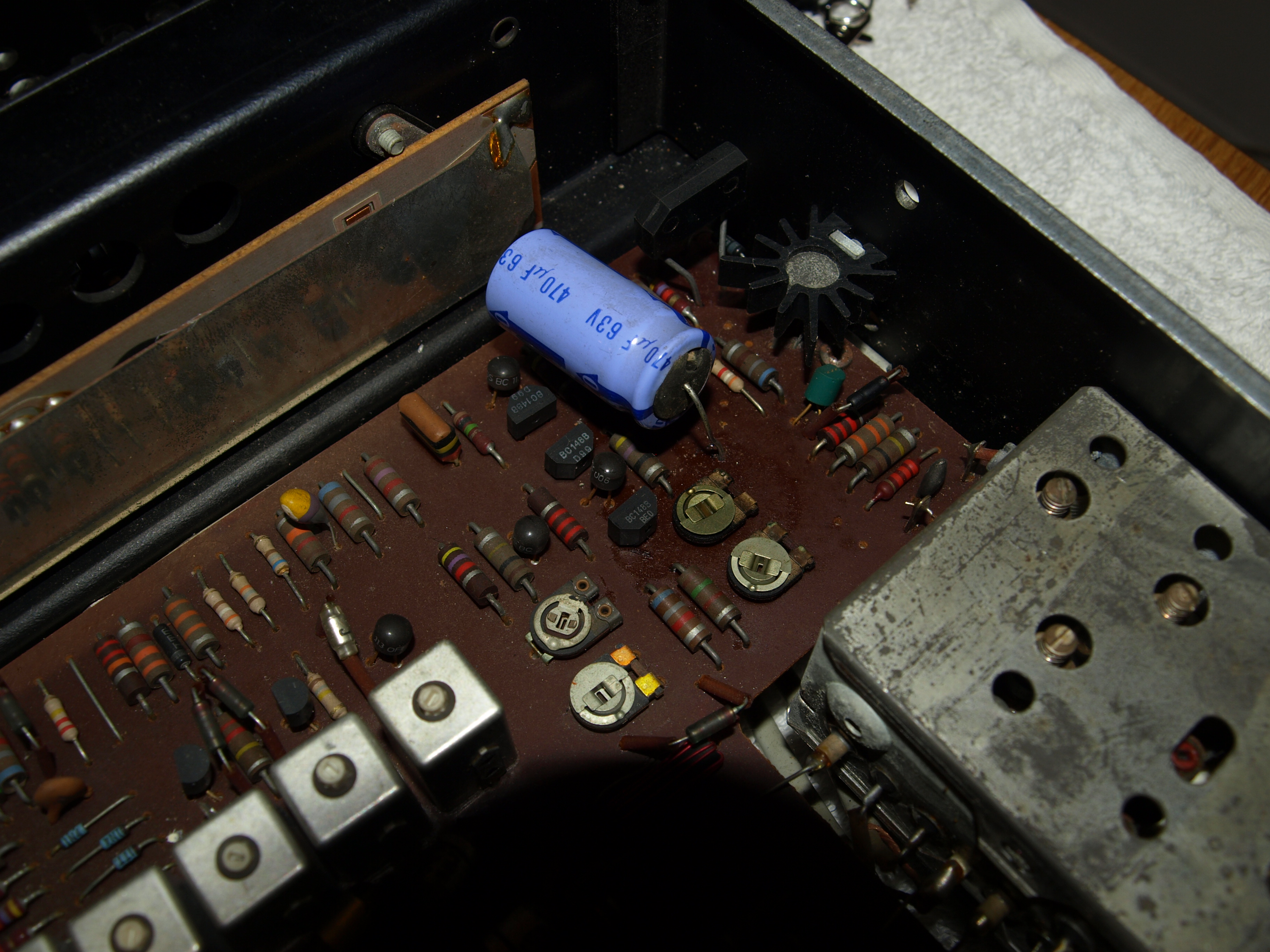
16 January 2026 at 10:56 #72594hcraig244SILVER MemberDusting out has revealed a probem in the 15v power supply, someone has been here before me and wielded a soldering iron, the smoothing cap that has been replaced has a loose leg!
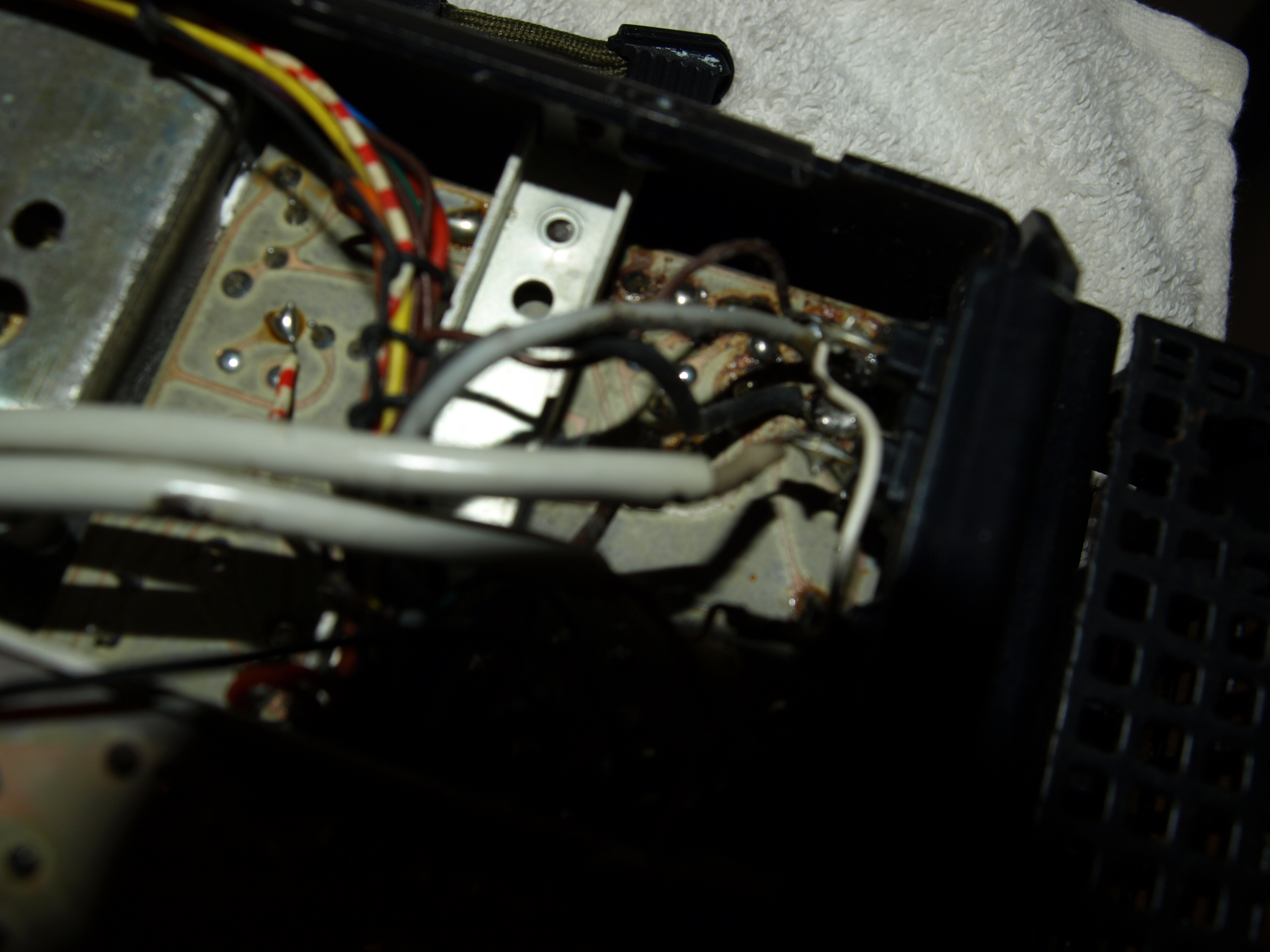
16 January 2026 at 10:59 #72597hcraig244SILVER MemberA look underneath reveals more potential horrors……
-
AuthorPosts


- You must be logged in to reply to this topic.