Home › Forums › Product Discussion & Questions › BeoMaster › beomaster 1000 ( type 2317 ) restoration & improvements?
- This topic has 12 replies, 4 voices, and was last updated 1 year, 6 months ago by
ummagumma.
-
AuthorPosts
-
9 August 2024 at 15:58 #58116
ummagumma
BRONZE MemberI picked up a beomaster 1000 type 2317 & want to restore it
The search function on the old archived forums doesn’t seem to work for me, so asking here: has anyone restored one of these, and if so are there any tweaks/improvements I can do to it?
Particularly interested in phono, maybe a better RIAA curve, and I’ll convert the non-preamp channel to regular since it’s obsolete now.
It is a very nice looking unit: at 20w paired with efficient speakers I bet it could work well.
Thanks!
10 August 2024 at 12:14 #58129Die_Bogener
BRONZE MemberSome years ago i repaired a BM1000. There are lots of Roederstein capacitors inside, red plastic caps. They were 40-50 years ago pretty good, this time is gone. Most of them are either dead or they spread acid on the board, they are cracked. Replace them all with Panasonic FC and FR types.
Surprisingly a lot of the soundpath is done with Tantalium Caps. This is probably one of the worst sounds ever. Tantal in the soundpath is no pleasure, Tantalium reacts different on the frequency, the inner resistor is not linear, it’s curved. Replace them with bipolar MKS WIMA Foil caps. MKS-2, MKP… whatever fits.
After this mod the BM1000 plays in a total different sound level. Much better.
The manual switches are a pain with hard grease. Clean it with contact cleaner and mechanical Oil like WD40. Some of the switches got stuck in the old grease. After cleaning and oiling all switches became smoth and reliable.
Good Luck!
10 August 2024 at 16:50 #58135ummagumma
BRONZE MemberThat is GREAT info, thank you!
I won’t even power it up before working on it: I found reference that one of the caps in the power supply tends to explode.
So I’ll do all that before plugging it in.
Guten tag!
12 August 2024 at 15:57 #58200Dillen
ModeratorWhat, in your opinion, would be a better RIAA curve?
Martin
12 August 2024 at 16:56 #58201ummagumma
BRONZE MemberI’ve seen restorations where new & better tolerance parts have been used to make the RIAA circuit more accurate, as well as improved the phono preamp.
So I was wondering if anyone had done that with the 1000
12 August 2024 at 17:34 #58202Glitch
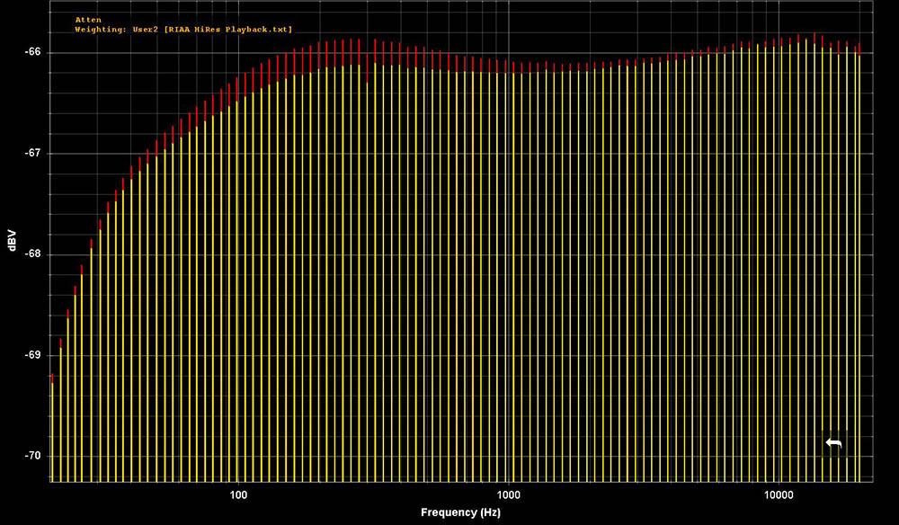
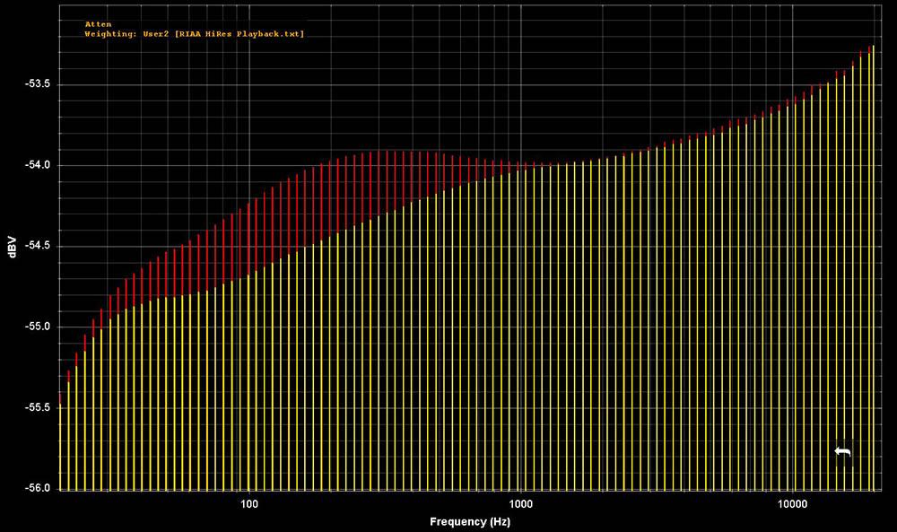
BRONZE MemberThe above plots are of the “deviation from ideal” for the RIAA amps of two different Beomasters. Areas of “improvement” could be to better match the curves to the ideal curve, make the left and right channels match better, or try to match the curve to a particular cartridge. Regardless of what your goals are, one will need a way of measuring the circuits to know if you achieved them.
Glitch
13 August 2024 at 04:52 #58221ummagumma
BRONZE MemberHey those are interesting, thanks!
I can’t figure them out though: are the 2 colors the left & right channels?
Or is one of the colors supposed to be the RIAA baseline? Because it doesn’t appear to match between the 2 images, although the graph scales are different.
Apologies if I’m missing something obvious
13 August 2024 at 13:52 #58243Glitch
BRONZE MemberThe green/red colors are for the left/right channels. The test is of a series of (nearly perfect) RIAA weighted sine waves being fed into the circuit board and the output measured. Each vertical line is the result at a given frequency. All of the bars at the same height would indicate that the circuit perfectly implements the RIAA curve.
The deviation from a flat response is the “tonal coloration” of the circuit. Differences between the green and red curves indicate that each channel has a different coloration.
This kind of plot can really highlight differences between circuits or issues within a given board. For example, the second plot was for a board that was recently recapped using fresh, high quality Panasonic electrolytic capacitors. This shows that you can’t just blindly swap parts and expect perfection. There may be variation in the new parts or another underlying issue in the other components. Another example would be if someone suggested component values based on the first circuit and you were working on the second circuit. I wouldn’t even want to try to guess what the final result would be.
Glitch
13 August 2024 at 17:16 #58252ummagumma
BRONZE MemberWow!! That’s quite amazing!
I wonder if testing it right after the RIAA & before the rest of the circuitry would be the best way to assess?
Otherwise tone controls, noise & interference from other things in the circuit would affect results?
I guess one could do both, to figure out what’s going on
13 August 2024 at 20:10 #58254Glitch
BRONZE MemberThe curves above are for just the RIAA stage.
You are correct in thinking that adding more stages would complicate any analysis. Testing smaller subsets also allows one to tailor the test to the component being tested. For example, testing the power amp stage is a quite different test than testing the RIAA or pre-amp stage.
I prefer to be data driven when doing repairs and modifications. I don’t think that there is anything particularly wrong with the swap parts and listen methodology if one likes the results. I just think that I reach my goals more quickly and with more confidence with test data.
Glitch
13 August 2024 at 20:45 #58255ummagumma
BRONZE MemberThat is definitely the way to do things…incredible. What software are you using to parse the signal & generate those graphs?
Have you ever gotten a flat result out of a RIAA preamp circuit?
As far as restoring the Beomaster 1000, I was planning on replacing most, if not all the caps, using the notes above by Die_Bogener, and cleaning/lubing the switches. Also checking for any notorious transistors.
If anyone else has improved the preamp ( or any other part of the unit ) I was hoping there was documentation somewhere to reference.
Not planning on messing with tuner alignment though as I don’t have the tools or knowledge, but any electrolytics in there might get replaced. Depends how it works.
I do have a sine generator and a scope although I have never used them. Maybe by the time I get this rebuilt I’ll try analyzing some parts of the circuit like that. Fascinating!
And thanks! Great food for thought
14 August 2024 at 14:45 #58277Glitch
BRONZE MemberWhat software are you using to parse the signal & generate those graphs?
I use a dedicated audio analyzer and use the software included with it. Prices and quality of audio analyzers vary greatly. Testing with general purpose test equipment and post processing the results is also a viable alternative. The price and quality of the general purpose equipment also varies greatly. What is more important than the price/quality of the particular equipment is that one understands the limitations of it and uses it accordingly.
Have you ever gotten a flat result out of a RIAA preamp circuit?
Everything is flat if you zoom out enough. Nothing is flat if you zoom in enough. I don’t worry that much about the “flatness” of vintage equipment. The “tonal coloration” of the old equipment is part of the charm that makes it interesting. I concentrate more of having the left and right channels match.
Maybe by the time I get this rebuilt I’ll try analyzing some parts of the circuit like that.
I try to repair the equipment just enough to get it working reliably. This usually consists of fixing the broken solder joints on the edge connectors, ensuring that the power supply voltages are correct, and adjusting the bias currents. I then do a baseline performance test (i.e. the “before” test). You can learn quite a bit at this stage. Sometimes this test reveals a specific issue that needs to be fixed. Other times, it reveals that a 60 year old piece of equipment is remarkably close to its original performance specification. It is much easier to do the “before test” before you swap all of the capacitors ;-).
Glitch
14 August 2024 at 23:03 #58290ummagumma
BRONZE MemberGreat tips, thank you for the explanation!
-
AuthorPosts
- You must be logged in to reply to this topic.


