Home › Forums › Product Discussion & Questions › BeoCenter › Beolink 7000 with Beocenter 9500 – Operational Conflict
- This topic has 10 replies, 4 voices, and was last updated 2 years, 2 months ago by
auric.
-
AuthorPosts
-
12 August 2023 at 07:19 #48203
auric
BRONZE MemberMy Beolink 7000 has stopped communicating with 9500 when it is on standby on the charging stand.
Previously it would continue to talk to the BC9500. Now it says “no contact.”
When I take it off the charger it will do two way with the BC9500.
When the remote is able talk to the BC 9500, selecting the “CLOCK” returns “operational conflict”
It is not the Beolink because it works fine with my BC 2500 2 way.
Another member experienced the same issue in 2016: the thread is here but there is no resolution posted:
https://archivedforum2.beoworld.org/forums/p/20679/170182.aspx#170182
Any ideas?
13 August 2023 at 19:14 #48204Die_Bogener
BRONZE MemberThere are some different software levels of the BL7000. Some are so old, that the BC9500 does not understand.
I have repaired some 9500 and some of my BL7000 did work with them, some did not. It depends on the software of the BL7000 … AND of the BC9500.
The BC can be upgraded, the BL7000 does not… SMD chip without socket…
The BC sends IR only from the front and the small sender horizontal IR beams.
The BL7000 has 2 IR receiver units… one horizontal and one vertical.
So… one is dying now on yours, probably the one when standing in the charger and the one looking to the ceiling is still alive…
Soooo, repair the smd caps in the metal box on the front…, dont wait, they are spreading acid over the ir transmitter chip. There is a time limit to repair when the acid is under this chip… then it is beyond repair. There is no way to remove the acid under the chip, it will only become better, but never again like new…
13 August 2023 at 20:34 #48205Inexperienced question: You say “repair the SMD caps” but your yellow dots are highlighting 5 of what look like ordinary electrolytic radial-lead caps? The two unmarked ones on the left (labeled “F” and one below) are flush like SMD pieces, but even they look likely to be ordinary electrolytics. So is this photo of your board *after* you repaired it, with your careful arrangement of the replacements and the yellow dots obscure the original square plastic bases? Or is this what it looked like originally, too?
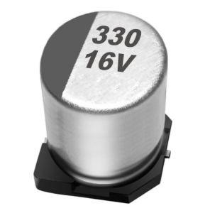
(For other novices like me, here is what a SMD electrolytic capacitor looks like:)
)
Please pardon the simple question; I have not yet dared to open mine!13 August 2023 at 20:41 #48206auric
BRONZE MemberHi Die:
Thanks for this. I think I will do this for preventative maintenance. But I don’t think its the BL 7000.
What’s strange is that the remote will see the Source and Volume but not always the clock.
So even off the charger, it will communicate with the BC9500 but show “operational conflict”. I also cannot program the BC 9500 clock with the remote.
So I think it is the BC 9500?
Derek
14 August 2023 at 08:31 #48207Die_Bogener
BRONZE MemberThe picture shows 5 positions of critical caps. After a repair… normal caps can be used, there is enough space for them.
“Clock” is different on the BL7000. There are 3 different software levels around clock. Even the glas plate is different because of this software difference.
Look for a newer Software Eprom for the BC9500.
Since i have no BC9500 i have never collected data for it…
15 August 2023 at 21:09 #48208auric
BRONZE MemberHi Die:
What are the values of those 5 capacitors?
- 22uF, 6.3V X 2 units
- 4.7uF, 6.3V
- 6.8uF, 6.3V
- This is the one inside the IR shield – Do you know the value?
Do you recommend sticking to 6.3V or go higher?
Thanks,
Derek
16 August 2023 at 08:19 #48209Die_Bogener
BRONZE Member6,3V is original for the SMD 22uF caps… but there must be a reason why they fail.
I use 16V-50V for these caps… the size is no problem, but shouldn’t be bigger than original.
The cap inside the shield is 4,7uF 25V … most actuell are 50V for this size.
4 September 2023 at 07:58 #48210auric
BRONZE MemberHi Die:
Do you happen to know the model/type of battery that inside the BL7000?
I should probably replace it along with the caps.
Derek
4 September 2023 at 08:50 #48211Die_Bogener
BRONZE Member21 October 2023 at 21:44 #48212lenhi
BRONZE MemberI am having trouble loosening the shield; I unsodered on three points, but the fourth is really hard to get at, and I do not want to destroy anything, obviously. Is there any trick to it?
Lennart
Location: Scania, Sweden
24 October 2023 at 04:29 #48213auric
BRONZE MemberLennart:
The easiest thing is to use a de-soldering iron with vacuum to remove all the solder from around the tabs of the shield.
When the solder has been removed you may have to gently bend the tabs of the shield with pliers while applying heat to align the tab with hole/slot in the circuit board.
Once all of the solder is removed it should be fairly easy to remove the shield.
Derek
-
AuthorPosts
- You must be logged in to reply to this topic.


 )
)