


Home › Forums › Product Discussion & Questions › BeoLab › BeoLab 8000: On Line/RCA input, always red LED ?
- This topic has 24 replies, 3 voices, and was last updated 1 year, 3 months ago by

-
AuthorPosts
-
4 December 2024 at 16:48 #61343
 BRONZE Member
Given you only have a basic multi-meter you could try the following, it is a long shot, but worth a try.
With a signal (music would be best) plugged into the phono socket use you multi-meter set to AC volts say 1 volt range if it has one, or the lowest available. What we are trying to do here is measure an analogue signal with a AC volt meter and compare the good speaker with the bad.
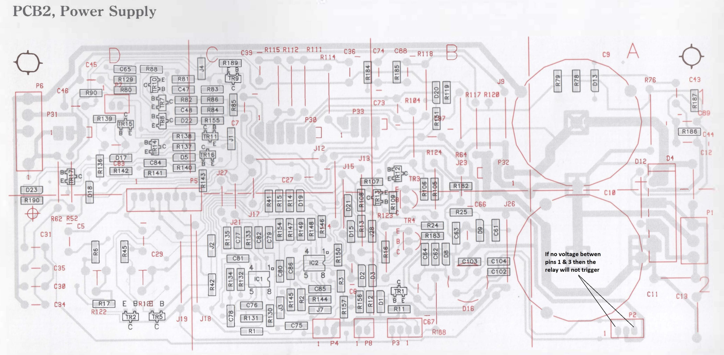
One meter lead on P2 pin 2 and the other lead on each of the following points on both speakers with the same music input.
- Both sides of C75
- IC1 pin1
- Both sides of R136
- Collector of Tr16
Note any points between the two speaker with a difference.
Location: Hampshire, England
4 December 2024 at 17:24 #61345GlitchBRONZE MemberWith a signal (music would be best) plugged into the phono socket
One could also use MP3 sine wave test tones which might make it easier to do comparisons.
Glitch
5 December 2024 at 12:40 #61354One could also use MP3 sine wave test tones which might make it easier to do comparisons. Glitch
Yes I agree..
Location: Hampshire, England
5 December 2024 at 17:28 #61358Thanks again gentleman!
I will start to measure between the ‘bad’ and a good speaker next week. As you suggested Keith, between P2 pin 2 and the listed components.
I have a sin wave app on my phone which I will use as a continuous audio signal.
To be continued!
Location: The Netherlands
Favourite Product: BeoSound 9000
My B&O Icons:
 12 December 2024 at 12:05 #61526
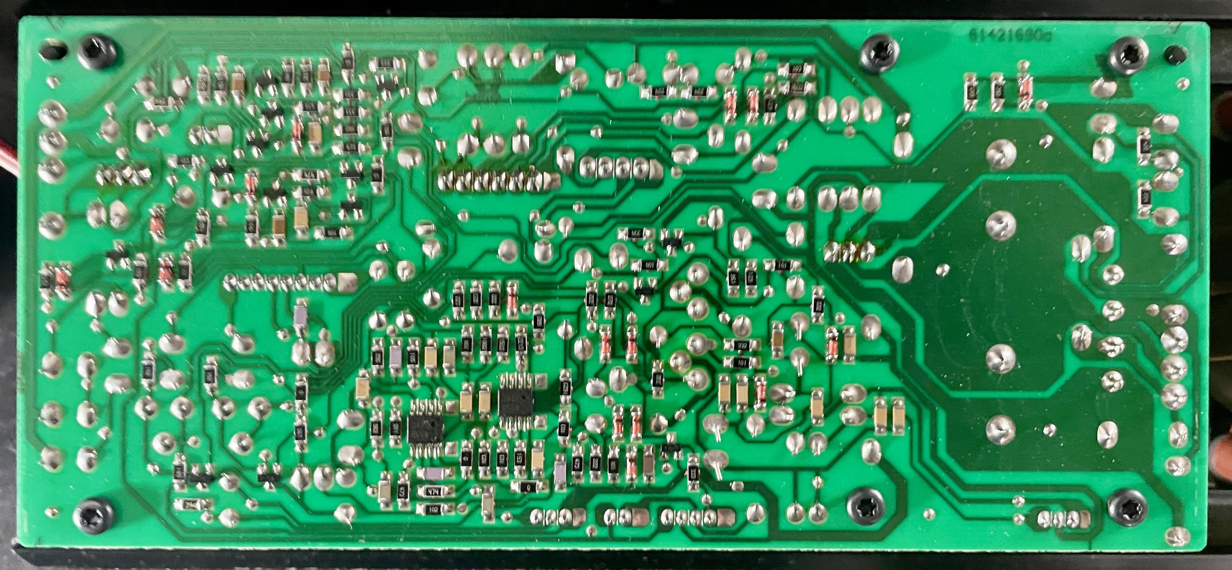
Today I tried starting the comparison measurements. As a reference / working speaker I wanted to use another BeoLab 8000 with serial 16xx xxxx. But I found out that the PCB layout of components is slightly different than the trouble BeoLab I am working on (13xx xxxx), and from the PCB02 drawing I have from the Service manual.
To show the difference: first the drawing of PCB02 I have from the Service Manual, and underneath a picture of PCB02 from the 16xx xxxx speaker I wanted to use for comparison.


IC1 is still clear, but I am not sure about the position of C75, R136, and TR16.
Question
- Could you help me find where these components are, or maybe you have a visual layout of this PCB02 version?
Location: The Netherlands
Favourite Product: BeoSound 9000
My B&O Icons:
-
AuthorPosts


- You must be logged in to reply to this topic.