Home › Forums › Product Discussion & Questions › BeoLab › BeoLab 8000: On Line/RCA input, always red LED ?
- This topic has 24 replies, 3 voices, and was last updated 1 year, 1 month ago by

-
AuthorPosts
-
24 November 2024 at 16:07 #61126
 BRONZE Member
Problem
I have a BeoLab 8000 (serial 14xx xxxx) with the following issue.
- When connected via RCA: the relay does not click in when a sound source is active.
- When connected via Powerlink: all works well both switching on as switching back to stand-by.
Things done/checked
- Foam-rot: there was foam rot, but everything has been cleaned. I have checked damage to copper traces on the PCB’s with magnifying glasses. No damage has been detected.
- Audio source & cable to RCA/Line: I have used different audio sources and cables. The input of audio signal is OK.
- PL/Line selector: Checked if it is in the right position for Line.
Tested from Service Manual (and others)
- Supply voltage: measured P2 Pin 2 to TR3 Emitter = 14.94v, P2 Pin 2 to TR4 Emitter = 15.07v
- Voltage between R83 and R86: measured 12.04v.
- Voltage TR11 Collector to P2 Pin 2 = 0.03v.
- P2 Pin 1 to P2 Pin 3 on PCB02 = 45v.
- P2 Pin 2 + TR1 Collector = 3.7v (I think it should be < 0.5v ?).
- P2 Pin 2 + TR 1 Base = 0v
- P3 Pin 1 + Pin 2 = +/-24.5v (I think it should be +/-15v).
- P1 Pin 2 + P3 Pin 1 = 52c AC (not sure what it should be ?).
- TR1 Base + P2 Pin 2 = 0v at Stand-by.
I think item 5 and 7 show the wrong values.
Tests focused on the Auto-start circuitry
Found input to test continuity between P7 Pin 2 (GND) and different components associated with the Auto-start circuitry.
- TR7 Emitter to P7 Pin 2 = Yes continuity
- TR8 Base to P7 Pin 2 = Yes continuity
- R81 to P7 Pin 2 = Yes continuity
- C47 to P7 Pin 2 = Yes continuity
- C65 to P7 Pin 2 = Yes continuity
- TR9 Emitter to P7 Pin 2 = Yes continuity
- R84 to P7 Pin 2 = Yes continuity
- Tr11 Emitter to P7 Pin 2 = Emitter No, Collector Yes, Base No continuity
Item 5 did not result in measured continuity.
Question
- What can be wrong, and how can I solve that the Auto-start will switch again on the RCA/Line?
- Might it be IC1 causing this issue?
Location: The Netherlands
Favourite Product: BeoSound 9000
My B&O Icons:
27 November 2024 at 14:32 #61175 BRONZE Member
In addition I did a test on the Input selector switch on PCB05, I measured all positions of the switch with a multimeter. And then did the same with a switch on a PCB05 from a working speaker. In comparison all results were the same.
I also swapped a PCB05 from a working system to this speaker. Results the same; in the RCA position the LED stays red.
To be continued when I received IC1.
In the meantime, still open to suggestions that help problem solving.Location: The Netherlands
Favourite Product: BeoSound 9000
My B&O Icons:
27 November 2024 at 22:07 #61198Glitch
BRONZE MemberI can’t offer any specific repair advice for the BL8000. However, I can provide some general advice based on a repair of a BL4000 with a similar issue.
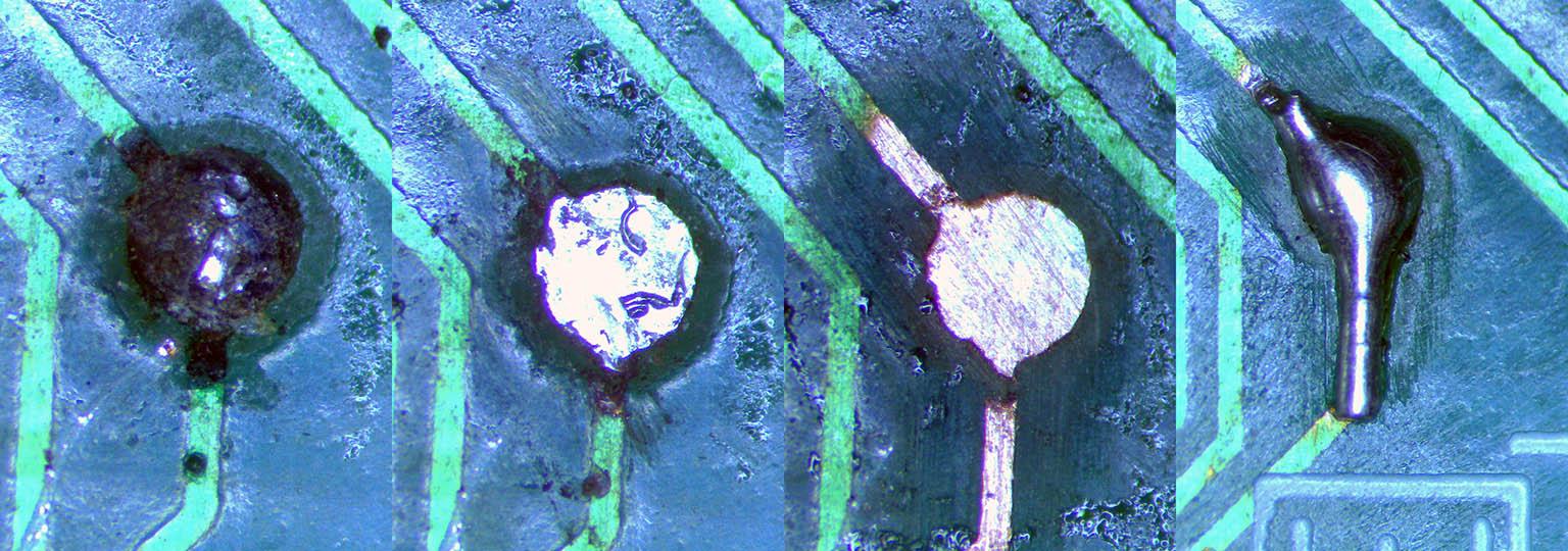
Based on my initial inspection, I didn’t think that I had an issue with foam rot, but I was wrong. I found several places where there was either open circuits or higher than expected resistance in the traces. Some of the telltale signs were black spots like in the picture below. Other places had white(ish) colored spots or were at the edge of a solder pad. The most insidious corrosion was where a trace ran under another component. Some of the breaks were not apparent until the area was cleaned with a scratch pen. I narrowed down the spots to examine in detail by installing needle tips on my multimeter probes and setting the meter to measure resistance (as opposed to using the “continuity beep”).
This picture shows a few of the steps in the progression of the repair. Note that the traces under the black spots ranged from being OK, to being partially corroded, to being completely corroded.
Hope this helps some,
Glitch
28 November 2024 at 08:56 #61204Whilst I have not needed to look at a Beolab 8000 for a very long time, I took time to remind myself of the workings of the circuit.
To answer your last question first, the problem could be IC1 and I noted you have tested all parts of PCB5 by comparing with a working unit.
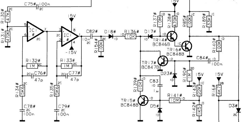
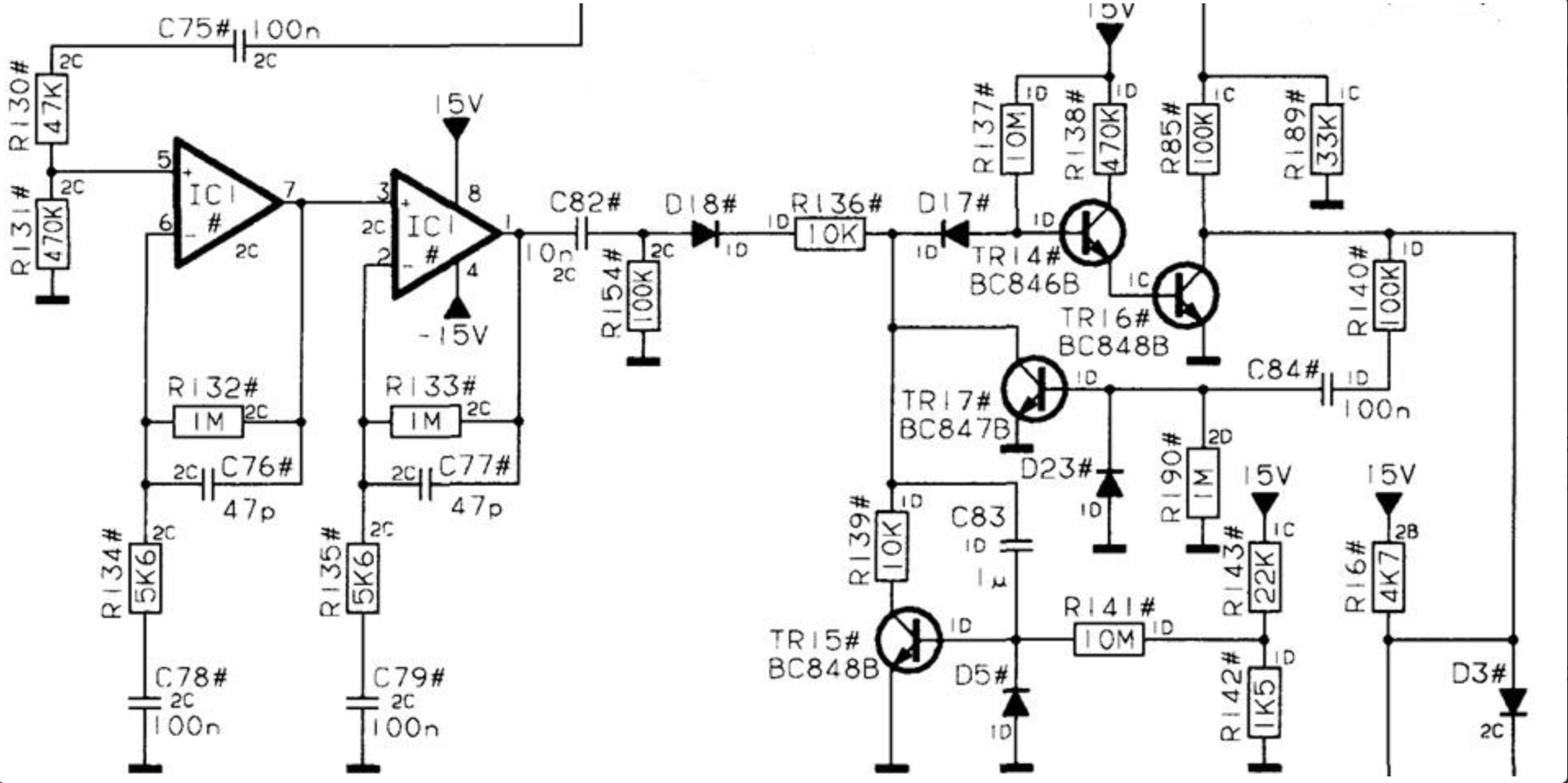
Given everything works perfectly with a Powerlink connection is helpful because that reduces the area for investigation considerably. The problem is almost certainly going to be prior to R85 on PCB2 where it feeds the base of TR9. The reason I say this is because where you use the Powerlink to switch on the speakers it forces the collector of TR16 which feeds the other end of R85.
If you have an oscilloscope I would look at the anode of D17 which is also the junction of R136 and the collector of TR17 with and without a signal at the phono input.
If you only have a multimeter, then the best way is comparing voltages between a good unit at the bases of TR14, TR16 and TR17 with and without a signal at the phono input.See attached circuit diagram of the area of concern
Let me know how you get on..
Attachments:
You must be logged in to view attached files.Location: Hampshire, England
28 November 2024 at 11:32 #61209 BRONZE Member
@Glitch: Thanks for your input and especially the visualization. This helps understand what to look for. So I will check again.
@Keith: Also thanks a lot!
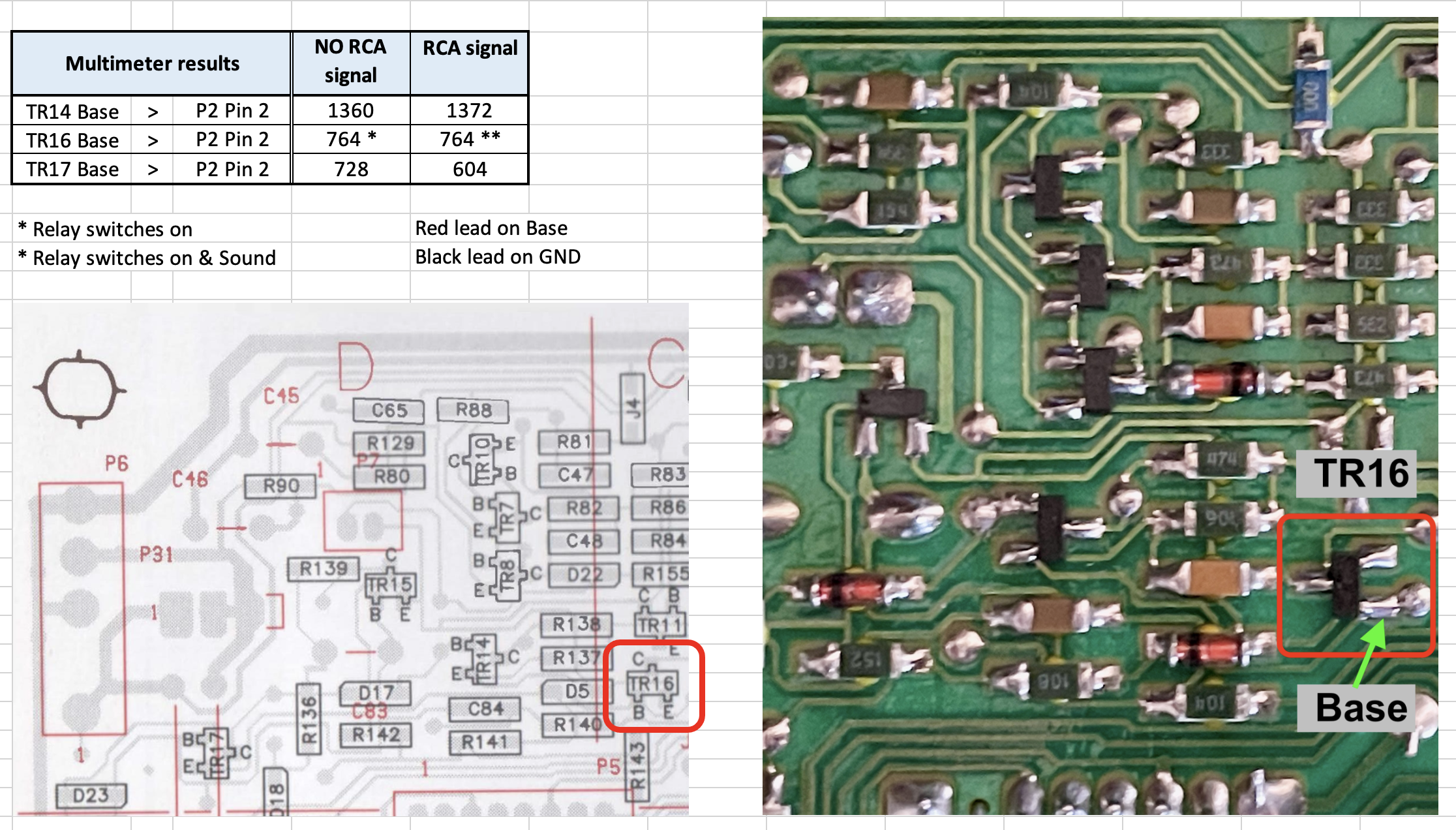
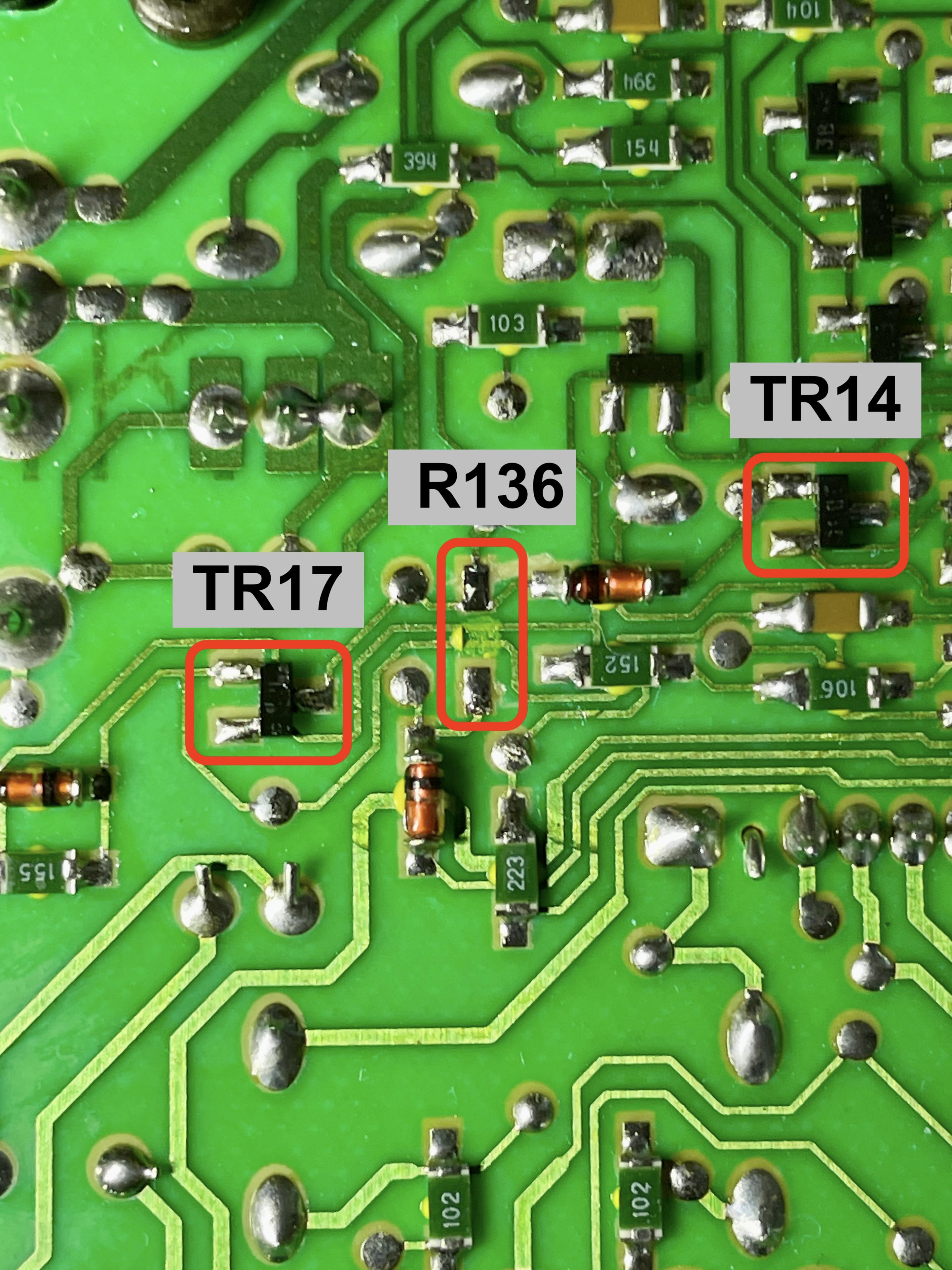
TR14, TR16 & TR17
In the meantime I measured what you suggested. Since I do not have an oscilloscope, I used a multimeter (Voltcraft VC130-1), in diode/continuity mode. IO found out that the direction of TR16 on my PCB is 90 degrees different than the layout in the Service Manual. But I assumed the Base to still be the left leg of the two next to each other.
You can see the results below. In all measurements, no continuity signal but a value measured.
Measuring at TR16 with & without signal on RCA, the relay switched on. With audio signal on the RCA, music was also there.Additional
In the schematics of PCB02, I read that IC1 should measure +15v at leg 8, and -15v at leg 4.
- I measured 29v.
As IC should also measure +15v at leg 8, and -15v at leg 4, I checked that one too.
- Also 29v.
Question:
- What does this mean to you?
- In the meantime I have also received a new IC1. Do you suggest to execute the replacement, or do you have another suggestion?
Location: The Netherlands
Favourite Product: BeoSound 9000
My B&O Icons:
28 November 2024 at 12:56 #61210You need to clarify your use of the words diode/continuity mode?
We are testing the DC voltage at each of these points..
Location: Hampshire, England
28 November 2024 at 13:07 #61211 BRONZE Member
@Keith: thanks, I guess I misunderstood.
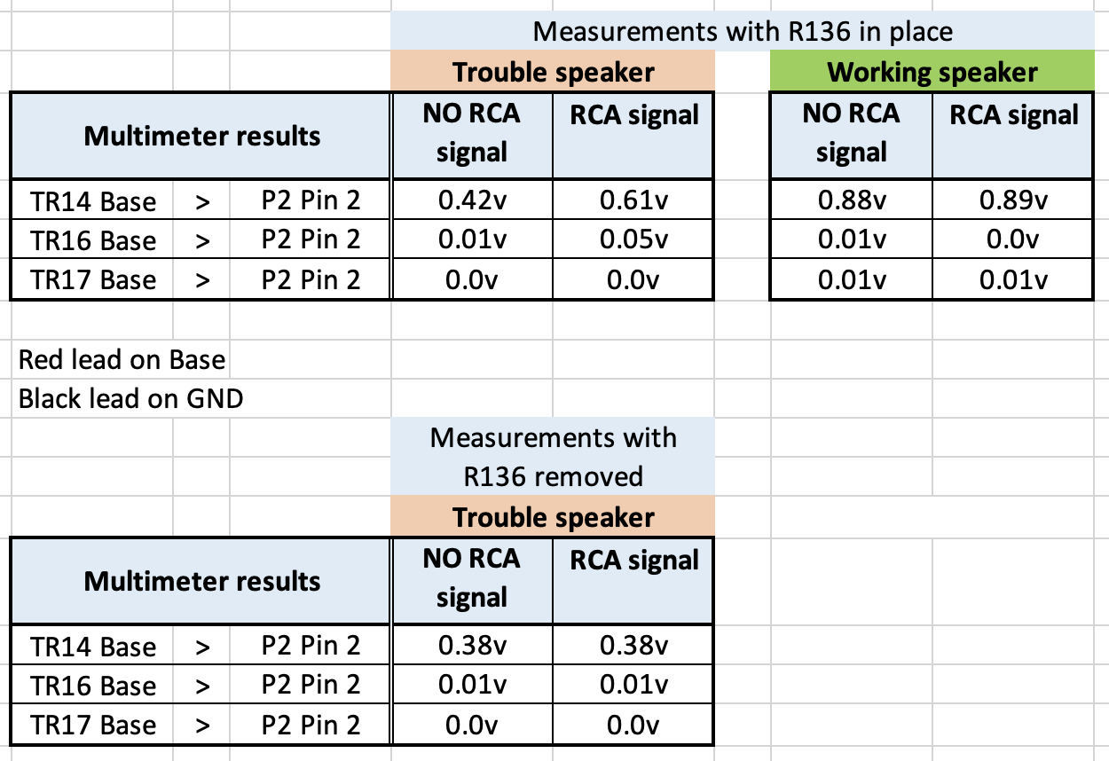
So I re-measured with the multimeter in DC voltage.
Also, I did the same measurement with a speaker that switches correctly on the RCA/Line-in.This is what you meant?
Location: The Netherlands
Favourite Product: BeoSound 9000
My B&O Icons:
28 November 2024 at 16:18 #61217This is exactly what I mean’t, thank you.
Clearly it is difficult without a scope and doing these voltage checks can only be a general guide.
However the 0.8 volts DC at the base of TR14 is much nearer to what I would expect.
It is starting to look like IC1 or one of the associated resister/capacitor around the IC could be at fault or well out of tolerance.
Before you change the IC1, lets do one other check by removing R136 add a input to the phono and measure the DC voltage at TR14 base again.
Location: Hampshire, England
28 November 2024 at 17:45 #61219 BRONZE Member
Thnx Keith, I will di that check and report it tomorrow.
Location: The Netherlands
Favourite Product: BeoSound 9000
My B&O Icons:
29 November 2024 at 10:01 #61224 BRONZE Member
Here’s the results of measuring TR14 at Base, after removing R136.
Curious to learn what the results mean.R136 removed.
Location: The Netherlands
Favourite Product: BeoSound 9000
My B&O Icons:
30 November 2024 at 16:22 #61240Thank you for your latest information.
Remembering that we are only measuring DC voltages meaning it can only show up general irregularities, not analogue signal..
The voltage at the base of TR14 is in line with what I would expect. This supports the likelihood that the fault is prior to R136 with further support from the fact that you accidently used you meter in diode/continuity mode which triggered TR16 and switched the unit on.
I am assuming that you previously check the +15 and -15 volts on pins 4 & 8 of IC1? That means between a ground point and pin4 and the same with pin 8
Whilst the problem could still be one of the components around IC1, you should change IC1 as the next step..
Location: Hampshire, England
30 November 2024 at 16:36 #61241 BRONZE Member
Thnx @Keith !
I just checked legs 4 & 8 of IC1 = +/- 28.8 volts
That’s quite different than the +/- 15 volts it should be …
Location: The Netherlands
Favourite Product: BeoSound 9000
My B&O Icons:
1 December 2024 at 09:22 #61249That’s because you have put your multi meter between pins 4 & 8 when you should have measured between ground point and pin 4 and again between ground point and pin 8.
Note my statement in the previous post which said “That means between a ground point and pin4 and the same with pin 8”
Location: Hampshire, England
1 December 2024 at 10:33 #61254 BRONZE Member
Thanks for your patience with me Keith. I am still learning, but I get this one.
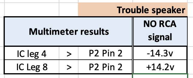
Here’s the new measurements with: the negative lead of the multimeter on Pin 2 of P2 for ground, and the positive lead to Leg 4 and Leg 8 of IC1.
Location: The Netherlands
Favourite Product: BeoSound 9000
My B&O Icons:
1 December 2024 at 12:47 #61259Whilst the Plus and minus power connections are a little low, it should still work..
You should change IC1 assuming you have the desoldering equipment available to do the job
Location: Hampshire, England
1 December 2024 at 16:43 #61261 BRONZE Member
Thnx Keith.
Swapping IC1 is on my list for tomorrow.
To be continued.
Location: The Netherlands
Favourite Product: BeoSound 9000
My B&O Icons:
2 December 2024 at 10:55 #61279 BRONZE Member
Update after replacing IC1.
Before replacing IC1 with a new one, I checked R136 which I had removed a few steps back. It still measured 10K ohm, so I put it back to position.
Then I removed IC1 and replaced it with a new one.
And of course I measured the voltage on leg 4 and 8: -14.3v and +14.2v. So exactly the same as with the old IC1.Just to be sure I also checked putting an audio source to the RCA/Line In; as expected, no switching on.
Question
- What would be the next step to check?
- If damaged copper traces (by foam rot) could still be a cause, in which part of the PCB do you expect those damages should be?
Location: The Netherlands
Favourite Product: BeoSound 9000
My B&O Icons:
3 December 2024 at 11:10 #61314I was afraid that would be your answer because operational amplifiers are normally very reliable.
With regards to damaged copper track caused by foam rot, yes that certainly could be the cause. Because the damage often cannot be seen, only a continuity test between each of the components in the circuit around IC1 and all the components around it will answer the question for sure. Also one of the capacitors could also be at fault or at least well out of tolerance.
Without an oscilloscope your work is now testing components typically by replacing.
Location: Hampshire, England
3 December 2024 at 11:36 #61315 BRONZE Member
Thanks again Keith! I hoped for a positive result with IC1, but I took into account that this would not be the trouble component. Nevertheless, we have come so far (at least in excluding trouble causes), so I will not give up.
Next step
Like you suggest, I will continue with continuity testing. To make sure I am looking at the right components to check …Question
Could you pleasde indicate to me, which components I should check, with the reference of the scheme (below) of the suspect area you posted before in this thread? (Take it as the way it takes the least time for you; either the components to check, or the ones I shouldn’t)Location: The Netherlands
Favourite Product: BeoSound 9000
My B&O Icons:
3 December 2024 at 15:05 #61317Glitch
BRONZE MemberKolfMAKER: Have you tried the “bad” PCB02 in the “good” speaker? Another thing that might provide clues is to do more mapping of the voltages at key points between the “good” and “bad” speakers. Do you have the equipment to “inject” a signal into the circuit. For example, remove C82 or R136, apply a voltage, and see the reaction of the downstream circuits.
Otherwise, I don’t have anything to add to the good advice that you have been getting from Keith.
Disclosure: I haven’t repaired any BL8000’s myself, so please give the opinions of those that have more weight.
Glitch
-
AuthorPosts
- You must be logged in to reply to this topic.


