


Home › Forums › Product Discussion & Questions › BeoLab › BeoLab 8000 modification: do you know this?
- This topic has 5 replies, 3 voices, and was last updated 1 year, 1 month ago by
 LeHe.
LeHe.
-
AuthorPosts
-
15 September 2023 at 04:10 #49007
 BRONZE Member
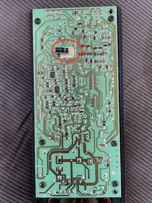
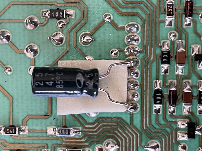
I recently saw a BeoLab 8000 with a capacitor added to PCB02. It looked like in the pictures below. I believe the capacitor is connected to two pins of the main IC.
Question
Does anyone know what kind of modification this is, or what it solves?

Overview

Close-up
Location: The Netherlands
Favourite Product: BeoSound 9000
My B&O Icons:
 16 September 2023 at 09:55 #49008Die_BogenerBRONZE Member
Is the crossover network still existing and fully mounted?
Otherwise ist could be a bypass for the crossover…
But it looks like a standard work of B&O… ???
Check, wether this cap manufacturer is also used on the board.
16 September 2023 at 15:24 #49009Thnx for responding Die_Bogener!
Answering your questions …
- Yes, the crossover network is existing and fully mounted.
- I am not sure if this is the standard work of B&O. I showed a picture to a former B&O repair engineer. He did not recognize this.
- The cap manufacturer I believe is different than what’s used on the PCB’s.
Location: The Netherlands
Favourite Product: BeoSound 9000
My B&O Icons:
16 September 2023 at 16:26 #49010Die_BogenerBRONZE MemberProbably the crossover ist defect or the one who did this wanted to change the sound.
Either more bass or treble… but without filter this is senseless and will destroy the speakers.
If it is treble: very nice to send low frequencies to a tweeter, this will extend lifetime… to some minutes.
And if it is bass: ok, this will kill the amp…
18 September 2023 at 15:13 #49011Thanks again for your comments!
I have removed the capacitor, to check if this made a difference.
Result = no difference. Sound is the same, functioning of the speaker system is the same.I will just leave it as is, without the capacitor. Probably better to avoid damage.
Location: The Netherlands
Favourite Product: BeoSound 9000
My B&O Icons:
17 February 2025 at 11:24 #63846LeHeBRONZE MemberCame across this old post.
This modification was also applied ex works to my 1995 1155 xxxx speakers. ( same construction)
Checking the PCB02 schematic shows that this capacitor 4.7 uF has been applied as an additional interference suppression and smoothing on the negative supply of – 15 volts.
I think that de reason for this modification was discovered during the final test of the product. Maybe interference or voltage dips.
So leave it as it was or rebuild it. The manufacturer did this for a reason and is not a hobbyist’s invention.
Attachments:
You must be logged in to view attached files.My B&O Icons:
-
AuthorPosts


- You must be logged in to reply to this topic.