


Home › Forums › Product Discussion & Questions › BeoLab › BEOLAB 6000: looking for DC voltage for DIY Bluetooth
- This topic has 13 replies, 5 voices, and was last updated 3 years, 7 months ago by

-
AuthorPosts
-
14 May 2022 at 05:58 #34802
With a single BeoLab 6000, I would like to try to built a Bluetooth module inside the casing of the BeoLab 6000. Here’s my idea:
- Audio connection – Connect between the RCA in the foot of the BeoLab and the audio input connector of the Bluetooth module. (Shielded cable)
- Power – Find a proper DC voltage from the BeoLab power supply.
The power is the point I am trying to find out. The Bluetooth module needs 5v DC at 800mA or 1A max.
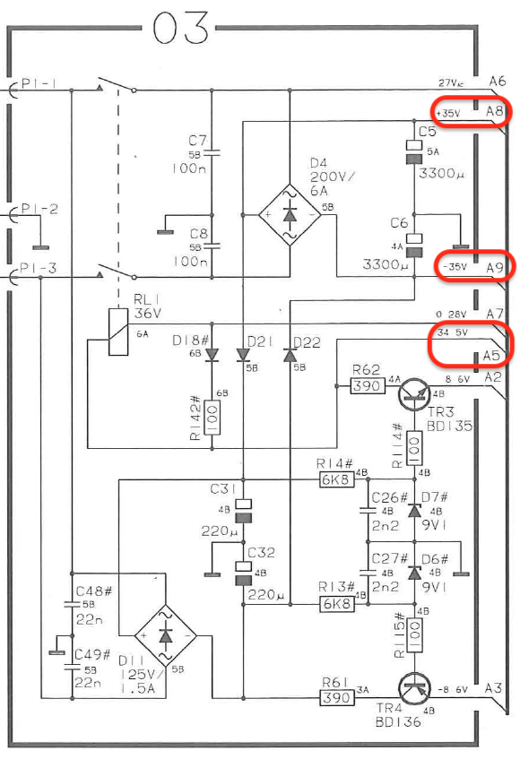
Most important, I need DC voltage that is continuously available, so also in the power standby mode when the LED is red.My options I think (refers to picture of PCB03 schematics)
- Take point A8 for +35v and A9 for -35v. And use an isolated DC/DC converter that brings it back to 5v DC (like the Traco Power TMR 4-2413WI).
- Use point A5 as it has 5v. I would prefer to take 5v as in this case I don’t have to add an extra DC/DC converter.
Questions
- Is point A5 a positive (+) 5v point and can I use this one?
- If I look at the schematics of the mainboard (see picture), I find it difficult to discover points A5, A8 and A9. Can anyone help pointing to the right point in this scheme?
(My questions are not bluetooth / signal strength / antenna related. I know how to handle that)


Location: The Netherlands
Favourite Product: BeoSound 9000
My B&O Icons:
 14 May 2022 at 19:40 #34803
 Moderator
Hi, nice project, but wouldn’t the bluetooth signal be too weak if the module is mounted inside the speaker?
Location: Paris France
14 May 2022 at 19:55 #34804Thnx Matador!
I am gonna use a small external Bt-antenna. Wire goes external via bottom to foot plate.But can you help find a DC voltage in the BeoLab 6000 that would work for me?
Location: The Netherlands
Favourite Product: BeoSound 9000
My B&O Icons:
17 May 2022 at 12:03 #34805@Damiendada
Do you mean, you are also looking for voltage points?
Location: The Netherlands
Favourite Product: BeoSound 9000
My B&O Icons:
17 May 2022 at 12:25 #34806I believe “damiendada” is some sort of spamer because his two post are just “I agree and was asking myself the same…”
KolfMaker, nowadays the PSU are small. I dont know about the empty room size into BL6000 bt couldn’t you fit a PSU, feed from the main power socket to the voltage you need and tuck it somewhere inside the beolab? That would also makes your mod totally independent of the beolab electronics and rule out any related problem if they happen?
Location: Paris France
17 May 2022 at 15:40 #34807Thnx Matador!
Concerning your PSU suggestion …
This is how I started, but I have had some issues with it. Adding a AC/DC converter that connects to the same power source as the BeoLoab 6000 itself, can cause disturbed audio signals. Many AC/DC converters work, but because they are switching PSU’s, they can cause ‘Ripple’ disturbances.
Therefor, I think an added wireless module can better be powered with DC voltage from the BeoLab 6000 system. This will be much cleaner.
Can you help me understand where such DC points on the PCB can be found, or do you know someone who can?
Location: The Netherlands
Favourite Product: BeoSound 9000
My B&O Icons:
18 May 2022 at 20:19 #34808pilatomicSILVER MemberHi KolfMAKER,
I checked out the schematic you posted, and at first the circuit around the 5V point was not make any sense. I believe it is rather a 34.5V point ! ( A2 and A5 are definitely 8.6V and -8.6V according to this schematic )
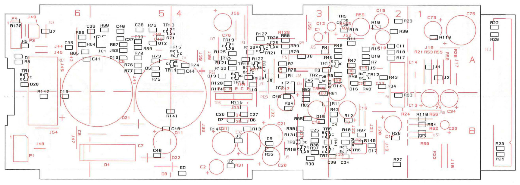
IMHO, your best option is to use the +35V present across the C5 capacitor ( it is the leftmost large red circle on the drawing ). You can find the negative side ( 0V ) by identifying the large white band on the capacitor.
Then use an isolated DC/DC to get a clean isolated 5V (you don’t technically need an isolated supply, but it makes things a lot easier to avoid noise and some issues with different reference potentials).
I would recommend the TMR 4-4811WI, as it accepts inputs from 18 to 75V.
Last advice : You might want to find a bluetooth module with a good quality audio output. Many of them are sub par, and would probably sound like a disappointment on those speakers.
Best luck with your project !
Location: France
My B&O Icons:
19 May 2022 at 10:59 #34809Just curious, Is it going to be a mono or left/right speaker? Most Bluetooth modules are stereo (which can be made mono), but when you aim for a stereo setup, how would that work? One module inside and linking to another?
Location: Utrecht
19 May 2022 at 12:15 #34810@Pilatomic: thnx!
In the meantime I ordered the Taco TMR 4-4811WI, and I have been able to make a test setup with all connected. This is what happens.
When I turn the system on:
- C5 +/- measure 35v, so that’s fine.
- The Taco output measures +/- 5v, so also fine.
Which means, when I plug in power on the BeoLab 6000, my wireless module gets 5v, and starts booting. Streaming music also works fine after the booting.
Problem
When I stop streaming music, the BeoLab switches back to stand-by (Green LED becomes Red).
But at that moment, the voltage coming from C5, drops from 35v to 30v. This causes the wireless module to reboot, which causes the auto stand-by switch back on (Red LED becomes Green).
Which means, this situation creates a loop. Every time music is stopped, the BeoLab returns to stand-by, which causes voltage drop and the wireless module to reboot, …. and so on.
Question
Maybe C5 is not the right point to take the voltage from.
- Is there any other point where the DC voltage is always available (also in stand-by mode (Red LED), and in a constant voltage?
- Where?
Location: The Netherlands
Favourite Product: BeoSound 9000
My B&O Icons:
19 May 2022 at 12:17 #34811It’s gonna be stereo to mono.
In this case I am not going to link two speakers to a stereo set.Location: The Netherlands
Favourite Product: BeoSound 9000
My B&O Icons:
20 May 2022 at 08:30 #34812pilatomicSILVER Member@Pilatomic: thnx! This sounds really helpful. One question. Is it correct that the +/-35v at the C5 capacitor is always available? So also when the BeoLab 6000 is in stand-by/Red LED on?
The voltage across C35 will only be present when the LB6000 is turned on. ( Relay RL1 closed )
If you need a permanent voltage, you can find it across C31. It will probably have quite a lot of ripple, but the DC/DC converter should be able to deliver a stable output voltage nonetheless.Location: France
My B&O Icons:
20 August 2022 at 13:45 #34813I am also looking for a permanent DC voltage on the BeoLab 8000. Can you help me confirm that?
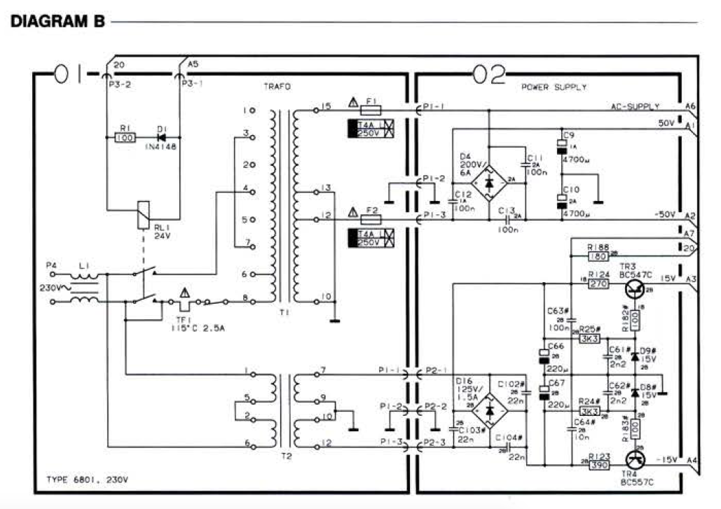
Is it 15v DC after capacitor C66?

Location: The Netherlands
Favourite Product: BeoSound 9000
My B&O Icons:
21 August 2022 at 08:46 #34814Die_BogenerBRONZE MemberBL8000: the standby transformer T2 has something like 2W available. Usually this transformer is very, very often defect of heat… and the power board is very rare. Usually found for 200,- replacement… if found. And used ones are not in good condition…
If the BT needs 5V 0,8A the transformer will not survive some hours… the transformer can supply 150mA in total. I had to replace last month a dozen of them … and new transformers that fit to the board are very rare and hard to get… out of production for 15 years.
There is plenty of room inside the BL8000 to install a quite normal PSU switch power supply in the upper loudspeaker area…
This one here was burning after 20 years…
21 August 2022 at 09:41 #34815Thanks for responding Die Bogener!
Questions:
- So you mean to say, the only way to get a permanent DC voltage is from the stand-by transformer? Or are there any other points which I could combine with a converter to bring it to DC 5v?
- I think I have a BeoLab 8000 here with a defect standby transformer. Is there any way I can get a replacement stand-by transformer?
Location: The Netherlands
Favourite Product: BeoSound 9000
My B&O Icons:
-
AuthorPosts


- You must be logged in to reply to this topic.