


Home › Forums › Product Discussion & Questions › BeoGram › Beogram 8002 not turning on
Tagged: 8002, Beogram, capacitor, power supply
- This topic has 30 replies, 5 voices, and was last updated 4 months, 2 weeks ago by
 Jordi Veytia Iglesias.
-
AuthorPosts
-
18 September 2024 at 20:54 #59181
 Jordi Veytia IglesiasBRONZE Member
Hello, I recently got a Beogram 8002. The issue it has is that it doesn’t turn on, not even the red standby dot.
I checked the insides and everything seems to be fine.Inside the power supply the fuse and the transformer do not seem to be damaged.
My guess is that the Wicon capacitor of the power supply is dead.
Does anyone know which is a good replacement capacitor?
Thanks 🙂
Attachments:
You must be logged in to view attached files.20 September 2024 at 12:47 #59209Hi Jordi
The Capacitor that you mentioned is the last I would change because this is the Phase Cap for the Platter Motor mechanism which normally lasts very long.
If you got no LED I would resolder ALL solder joints of the plugs on the PCB’s an performing a recap of ALL electrolytic capacitors on thePCB’s.
Usually after that the BG 8000 will start up again…following issues have to be inspected later.
Here, on Beolovers site, you will find a bunch load to read about restoring the BG 8000
https://beolover.blogspot.com/p/beogram-80008002-restoration.html
let us know about your progress
Kind regards
Christian
6 December 2024 at 22:33 #61393Francois LemahieuBRONZE MemberHi Jordi, have you made some progress since then?
I have no experience whatsoever in fixing a Beogram 8002 and I certainly don’t mean to question Christian’s advice. I am starting looking into my Beogram (which used to be my father’s) as it went down a couple of months ago (same issue as yours, no standby dot). Given my father got it firsthand, I plan to test the power supply first (I have never tried resoldering before and don’t plan to give it a go on the Beogram). In case the capacitor happens to be the defective part, I have seen that beolover has a fancy replacement part for sale here: https://beolover.com/products/motor-capacitor-for-beogram-8000-and-8002?srsltid=AfmBOorVVyq1ac6mtxyNRzYs3qntusTpMdpkbGvgwSCFO5RvZbALmjbR
Francois
6 January 2025 at 22:38 #62364Jordi Veytia IglesiasBRONZE MemberHi Francois, I haven’t made any progress on my Beogram. I got the parts Christian recommended, but I haven’t got to the soldering yet.
I’ll venture into re-soldering the capacitors and in case that ends up not being the issue I’ll replace the one in the power supply.
I’ll keep you updated once I get to it.
Thanks for the advice and good luck with yours.
Jordi
30 August 2025 at 00:30 #69182Jordi Veytia IglesiasBRONZE MemberHello, how are you?
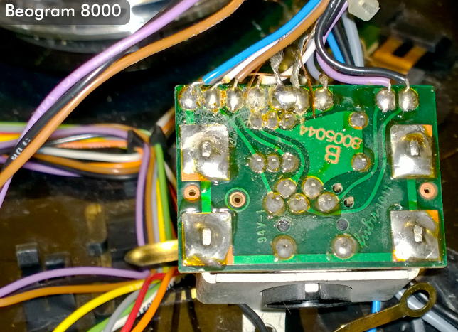
I’ve been replacing all the capacitors on the PCB. But I have one question. In the instructions that came with the capacitors for the Beogram 8002 from Beoparts shop, it says that on C27 an additional connection should be introduced, linking the negative pin of C27 to the negative pin of C20.
I know there are different versions of the PCB and the instructions do not specify if this additional connection should be done on all versions or just in specific ones. I do notice that my PCB is slightly different from the one shown in the instructions which is why I don’t know if I should introduce the new connection.
Anyone knows if this applies to all versions or just some of them?Thanks 🙂
Attachments:
You must be logged in to view attached files.30 August 2025 at 06:52 #69204There is no harm in adding that jumper as it is simply connecting two ground points together. These boards being single-sided used jumpers all over the place to connect grounds together.
1 September 2025 at 19:44 #69293Jordi Veytia IglesiasBRONZE MemberGreat! Thanks for the response. I’ll add the jumper then.
Thanks 🙂
2 September 2025 at 02:56 #69301Jordi Veytia IglesiasBRONZE MemberHello, how are you? I have replaced all the capacitors following the cap replacement kit from dksoundparts.
Is there an additional step I should follow before plugin it in? What should I expect to see after plugin it in, red standby light?
If I get no signs of life should I move ahead and replace the Phase Cap for the Platter Motor mechanism?
Thanks 🙂2 September 2025 at 04:44 #69302First I would double check that All of the replaced capacitors are in the correct polarity. After plugging in, you should see a red dot in the display. If you are not getting that I would check that you have 5VDC at pin P6-1 which is powering the CPU, then work backwards to the Zener and regulator.
2 September 2025 at 23:35 #69322Jordi Veytia IglesiasBRONZE MemberHow should I proceed in order to test 5VDC at pin P6-1. I have identified the location of that pin, but where should I contact with the other probe in order to test the voltage? Sorry for the dumb question 😬
Thank you very much.
3 September 2025 at 00:39 #69326You need to connect the black lead to a chassis ground which is available many places. For example, the negative terminal of C24 or C27.
3 September 2025 at 23:41 #69346Jordi Veytia IglesiasBRONZE MemberThanks, just checked for 5VDC at pin P6-1 with the black lead on negative C27 and got no signs of life.
I also want to share that the din plug is completely disconnected, the guy I bought it from told me he wanted to replace it with an RCA but never did. Anyway, the din plug is not connected, do you know how to reconnect it? I’m attaching an image.Thanks
Attachments:
You must be logged in to view attached files.4 September 2025 at 06:59 #69353Looks like someone did a nice hack job. Here is a link to a picture with all the wires on the correct pads: https://archivedforum2.beoworld.org/cfs-filesystemfile.ashx/__key/CommunityServer.Components.PostAttachments/00.00.12.47.75/bg8000_5F00_din_5F00_pcb_5F00_01.jpg
4 September 2025 at 15:20 #69367Jordi Veytia IglesiasBRONZE MemberThank you very much! I’ll reconnect everything and run the test again.
🙂
10 September 2025 at 02:53 #69524Jordi Veytia IglesiasBRONZE MemberHello, just sharing an update. I’ve reconnected the severed Din plug. However, I still get bored dot when plugging, no 5VDC at pin 6-1, nor voltage at the 5V regulator. I’ve checked all new capacitors to be installed correctly, but no signs of life.
Any other suggestions? Should I go ahead and try replacing the Wicon capacitor inside the power brick?
Thanks 🙂10 September 2025 at 03:35 #69525That capacitor is not your problem. You say you don’t have voltage at the 01C1 5V regulator. Does this mean that you measure 0V at both its input and output? If that is the case can you check the continuity of the F1 fuse? If it is good that means you have no output out of the diode bridge and its supporting capacitors. That’s where I would focus.
12 September 2025 at 01:24 #69561Jordi Veytia IglesiasBRONZE MemberHello, checked all the fuses and the one inside the power brick has no continuity. Going to replace it and will run the tests again.
I’ll keep you posted.Thanks 🙂
24 September 2025 at 01:40 #69870Jordi Veytia IglesiasBRONZE MemberHello, I’m back with an update. I have replaced the fuse and I now get 5VDC at pin P6-1 and on the 01C1 5V regulator. But still no red dot 🙁.
So far I’ve replaced the fuses, replaced the capacitors, checked their correct polarity and re-install the severed din plug.
Any ideas what else could be the issue.
None of the buttons do anything either.
Thanks 🙂24 September 2025 at 05:12 #69872Most of the time with these models it is an issue with the ribbon cables between the main board and the other ones including the keypad. I would carefully reflow all of the connections on each cable end. I would also check if your 2MHz clock is running on Pin 11 of IC1.
4 October 2025 at 04:00 #70109Jordi Veytia IglesiasBRONZE MemberHello, how are you? Just wanted to share great news. I managed to bring it back to life! 🙂
The issue was oxidized base for the IC1 and a bad TR17. I replaced it and cleaned each slot for the IC1 with Deoxit.
I now have the issue that the belt is to loose so the motor slips when trying to move the carriage.
Do you know if anything from the carriage mechanism needs to be lubricated? And if so which lube should I use?
I connected it to a pair of speakers and I do get sound when I gently tap the stylus. But there’s a general background humming sound that’s getting in from the carriage motor.
Any suggestions to clean the sound?
Anyway, I consider getting to this point a great success for a Facebook Marketplace facing landfill.
Thank you all for all the support so far, I would have been able to get this far without your support.
🔈🎵Attachments:
You must be logged in to view attached files. -
AuthorPosts
- You must be logged in to reply to this topic.