


Home › Forums › Product Discussion & Questions › BeoGram › Beogram 4000….an old friend
- This topic has 33 replies, 1 voice, and was last updated 2 years, 1 month ago by
 hcraig244.
-
AuthorPosts
-
12 December 2023 at 09:02 #51182
 hcraig244SILVER Member
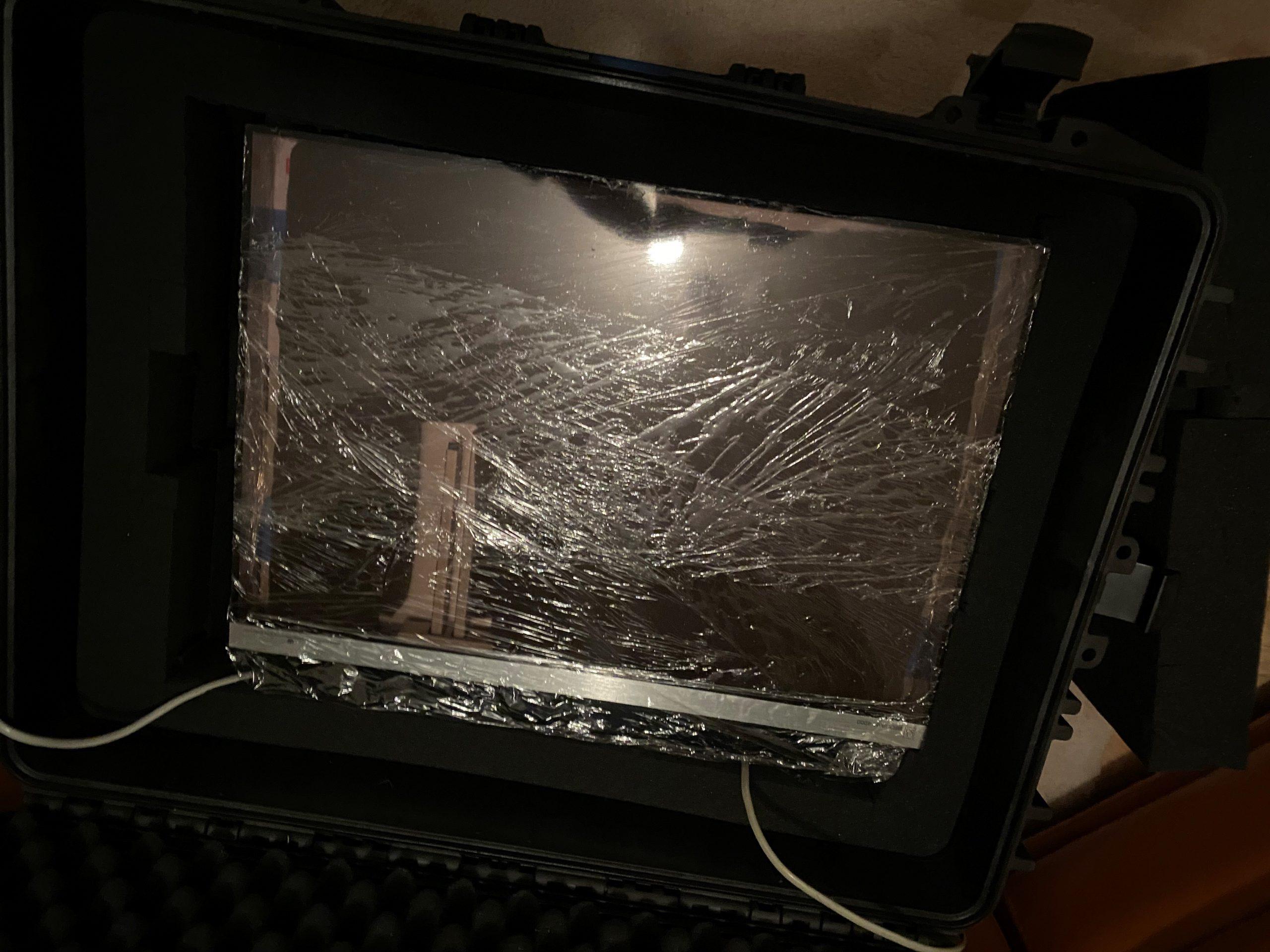
A rather large and heavy armoured chest was delivered yesterday…..
12 December 2023 at 09:15 #51183hcraig244SILVER MemberAnd inside the chest was a heavily padded BG4000….
12 December 2023 at 10:39 #51184hcraig244SILVER MemberNot a particularly good image but does show the extent of the protection the chest provides for these delicate machines…given the degree of abuse they would suffer at the hands of almost all delivery companies
 12 December 2023 at 11:04 #51185hcraig244SILVER Member
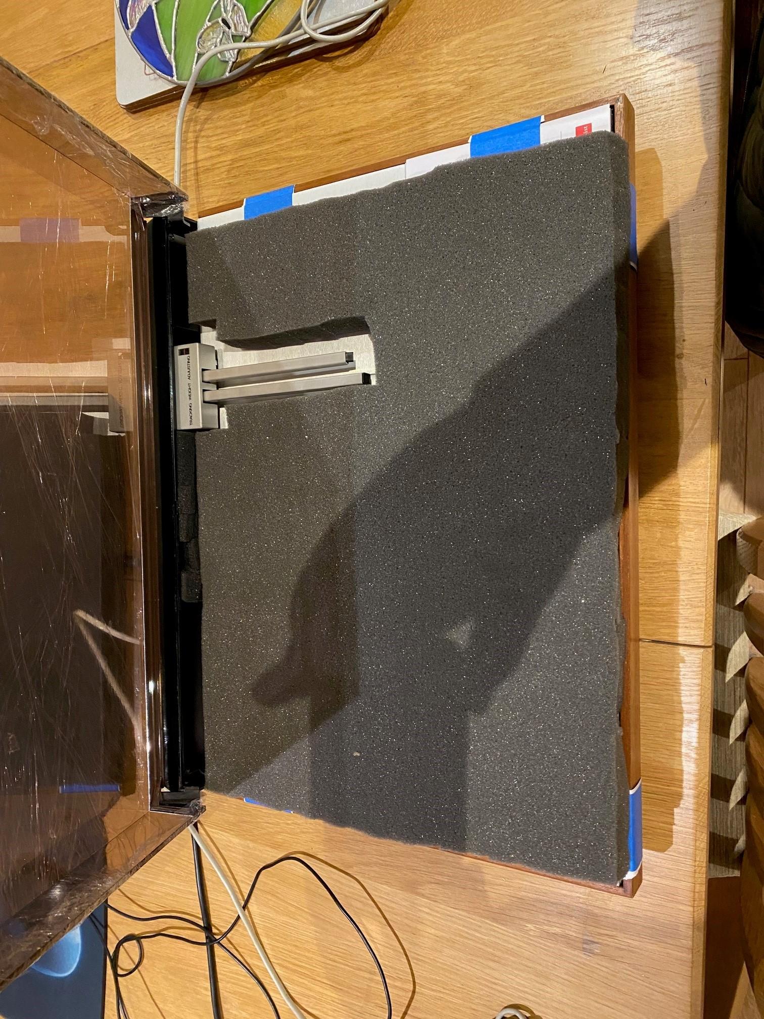
Lifted out …..
 12 December 2023 at 11:44 #51186hcraig244SILVER Member
Well secured and packed…..platter was packed separately and stowed away under the Beogram in foam and cardboard
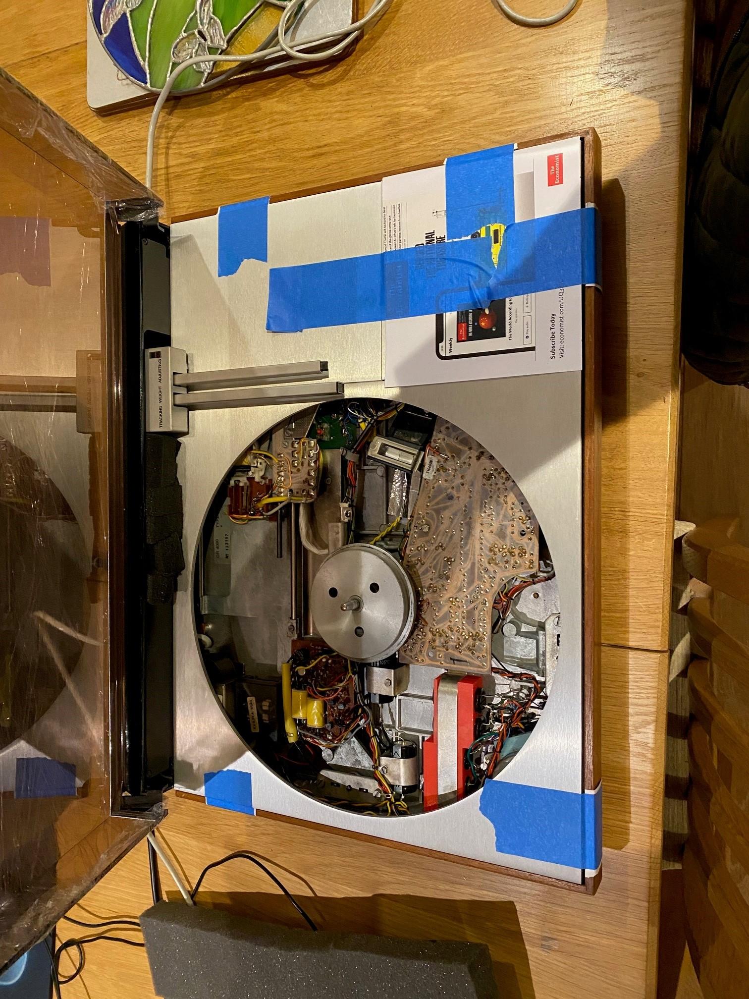
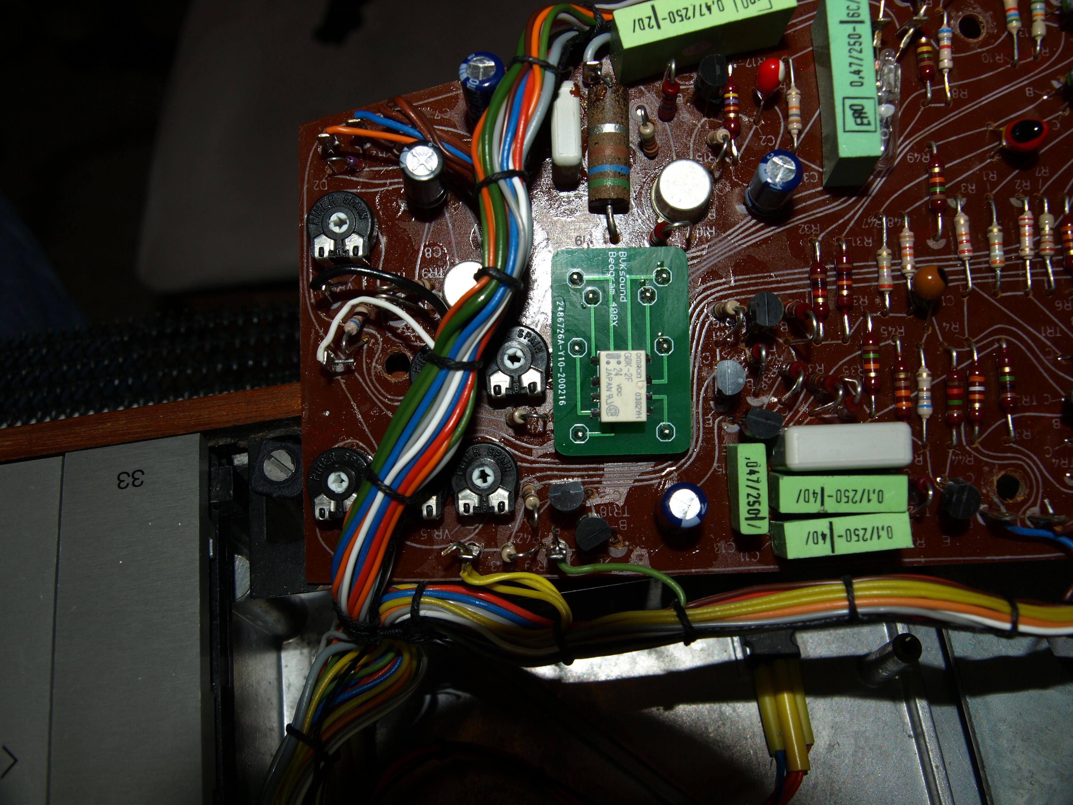
12 December 2023 at 13:58 #51187hcraig244SILVER MemberBeen here before as can be seen from the Rudi patented laser printed capacitor bracket, and the ne 6v & 24v power supply smoothing capacitors….cant quite remember what else I did in here but I suspect it may have been a replacement of the 24v regulator OTR1….It comes with the description of “misbehaving” in as much as the tone arm is driving inboard and not returning to the stop position when required….I will have a look.
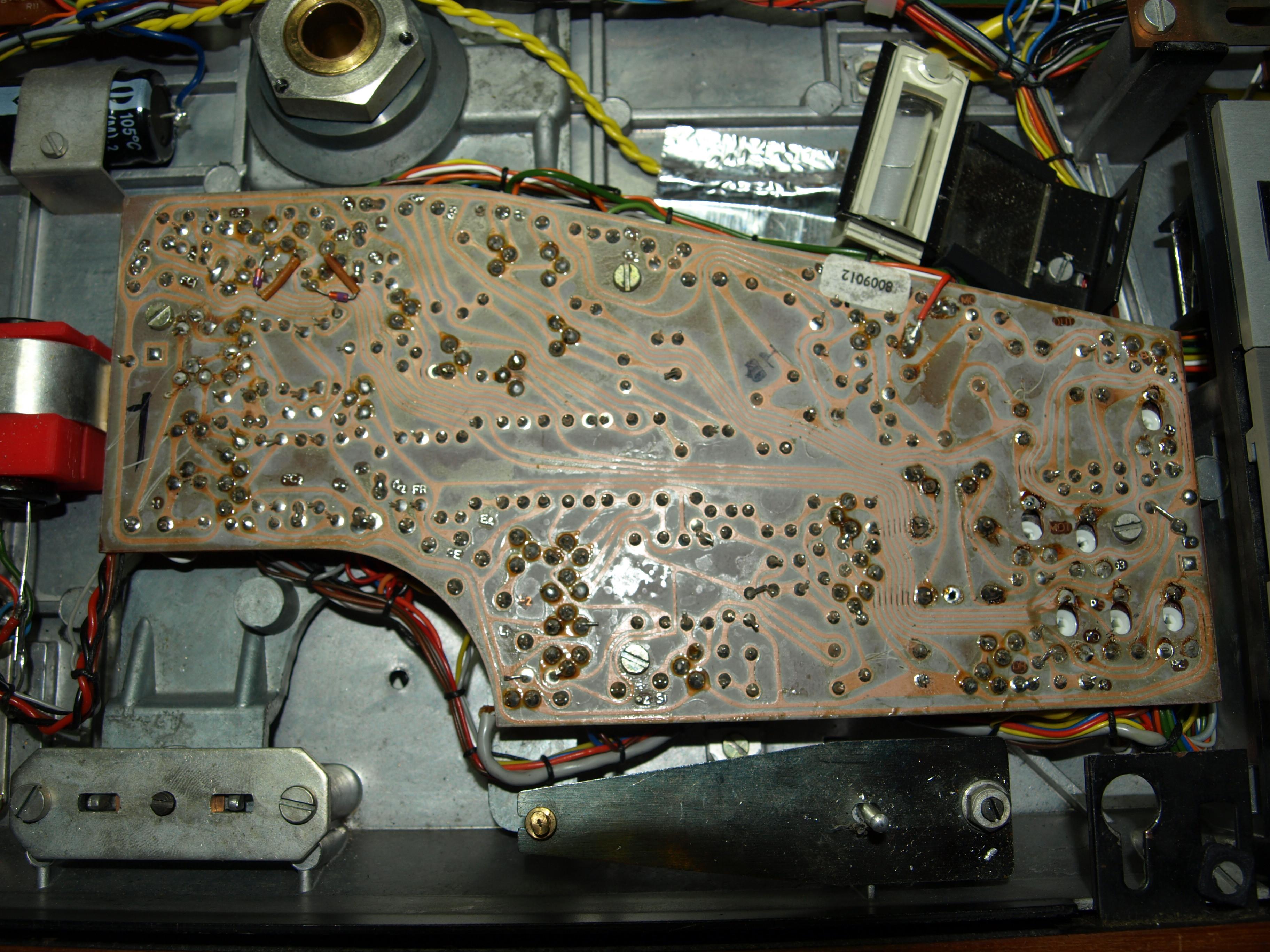
16 December 2023 at 12:49 #51188hcraig244SILVER MemberOk…..opened up and a visual inspection prior to power on reveals only one screw holding the main PCB in place….not a very encouraging start.
16 December 2023 at 12:52 #51189hcraig244SILVER MemberIts doubtful I would have missed the absence of said screws so im suspecting a third party involvement somewhere…..
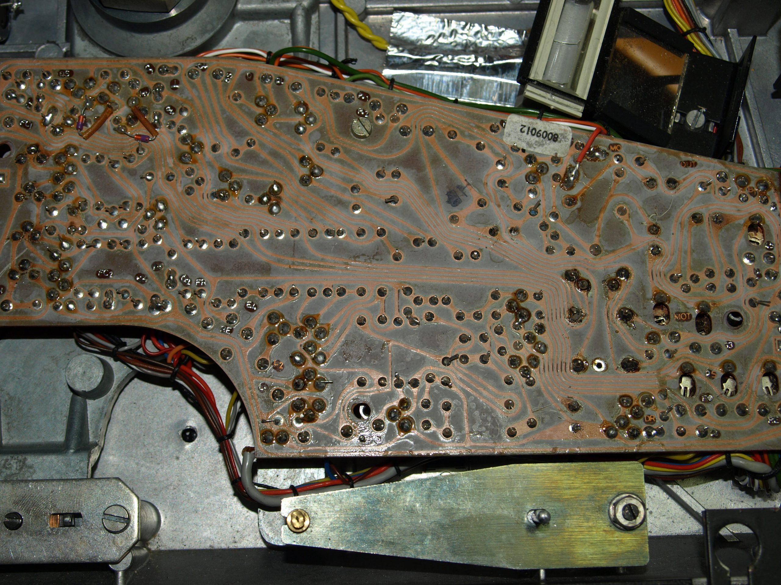
16 December 2023 at 13:04 #51190hcraig244SILVER MemberQuick look under shows signs of activity….looks like 1TR29 and 1TR30 have been replaced with something else…also the speed control relay has been replaced….
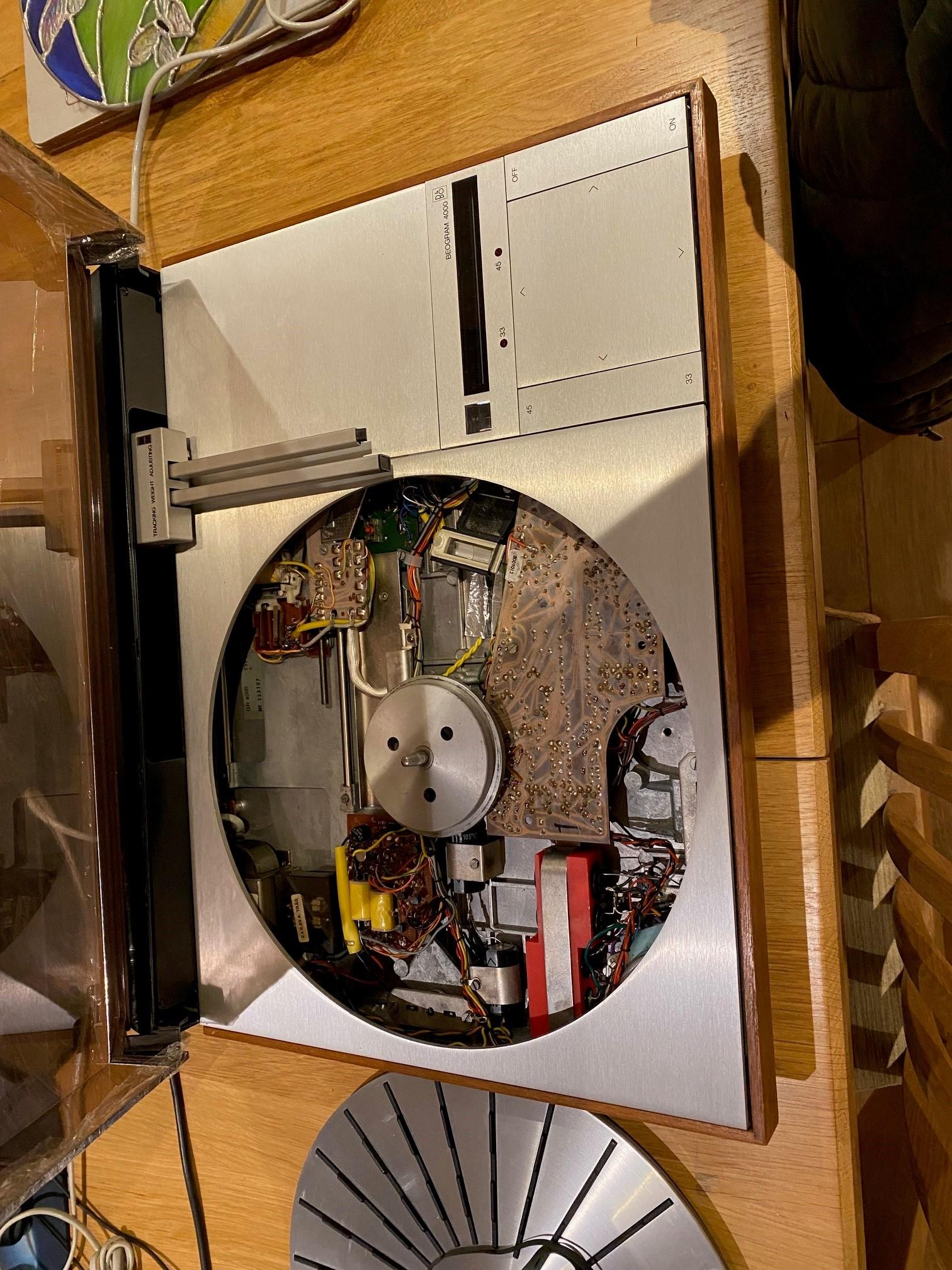
16 December 2023 at 13:16 #51191hcraig244SILVER MemberPut the PCB back and got the variac out…….with the meter in series slowly powered up, the multivibrator circuit clicked on and there was no smoke or crackle of unhappy components..current draw was around 20ma…
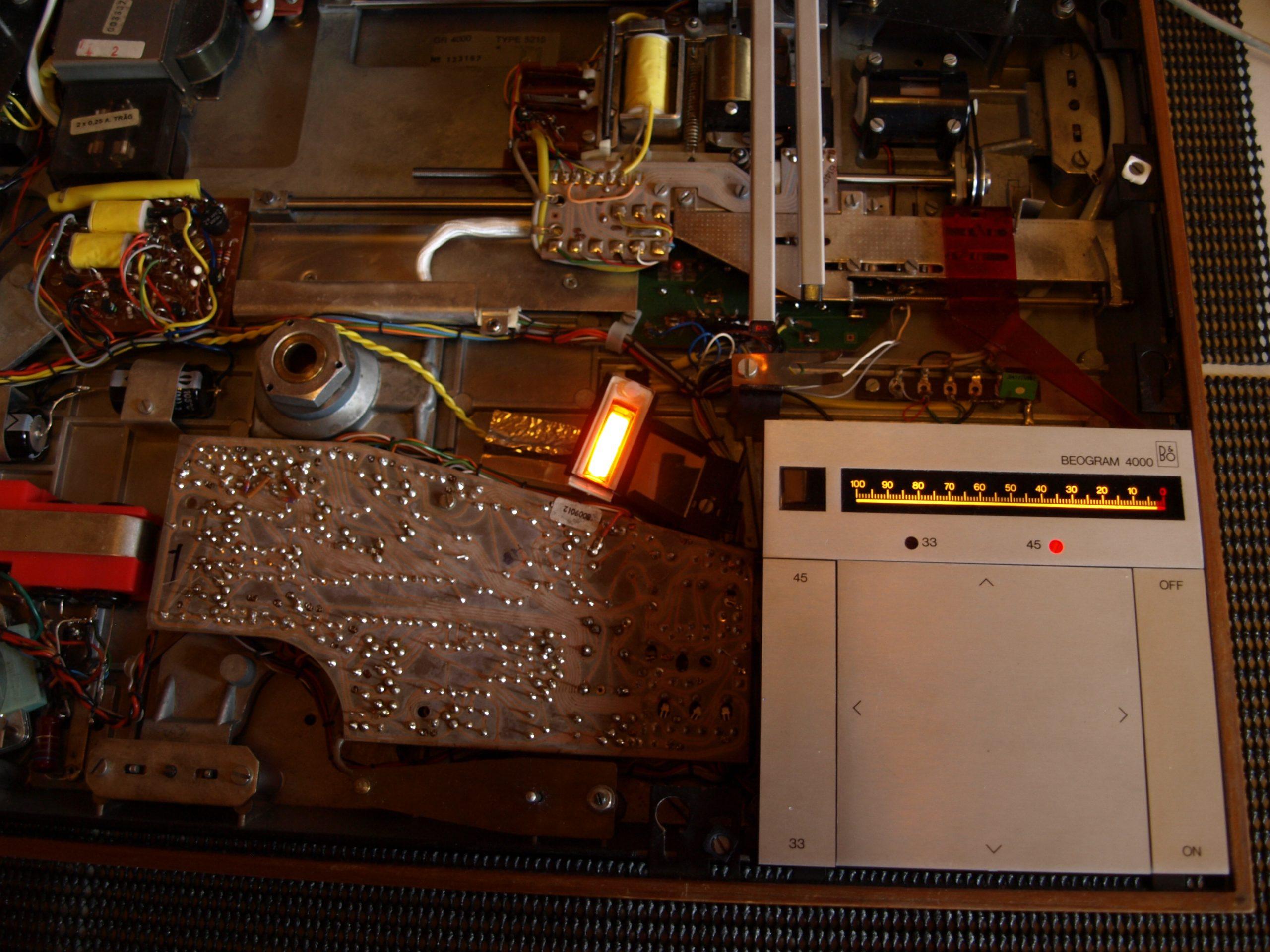
16 December 2023 at 13:28 #51192hcraig244SILVER MemberHit Start and the neon lamp came on, always a good start….the 45rpm lamp also lit up and the main motor started to revolve….scale lamps also illuminated…all good stuff, however the solenoid energised straight away and the tracking motor sat motionless….a small push inboard did nothing….a small push outboard momentarily powered the tracking motor, the carriage didnt move as the belt to the pully was just slipping too much to get any traction.
So……quite a bit to sort out, I suppose the main good thing is that all the vital components, transformer/motors/solenoid and I did notice the detector arm lamp was lit/ are all healthy…they just seem to have “lost there marbles”.
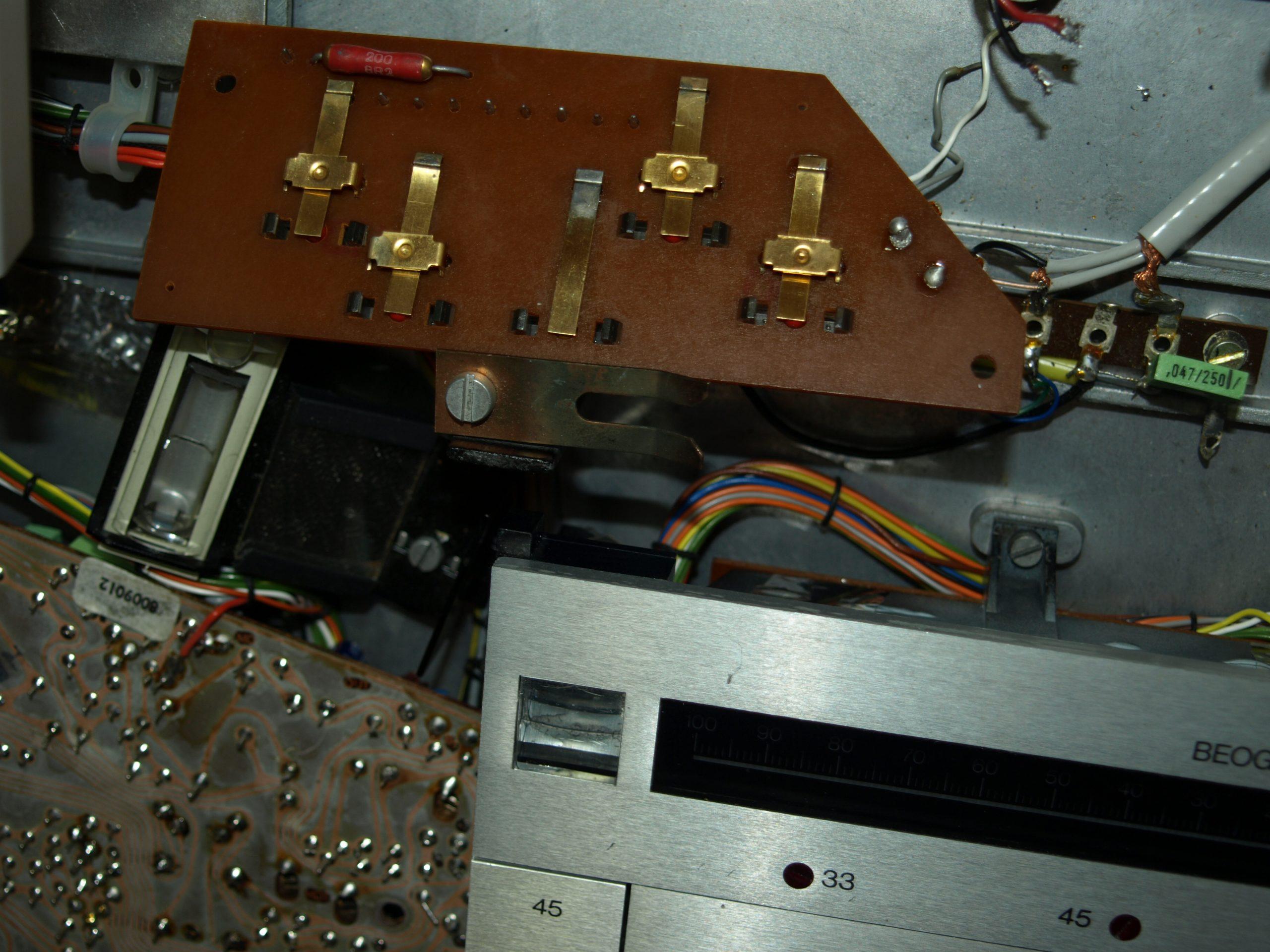
I will start by examining the slider switches as they often seem to be behind a lot of issues with these decks…..as always comments and advice is welcome ;¬)
17 December 2023 at 14:01 #51193hcraig244SILVER Memberspent a little time this morning unsoldering and cleaning the transport slide switches, didnt look bad actually….I think someone may have gold plated these ;¬) but cleaned them to eliminate them from any further considerations.
17 December 2023 at 14:10 #51194hcraig244SILVER Memberfollowing re solder of the transport motor connections powered up again and the following happened….Main motor started to run, Neon lamp illuminated, scale illumination lamps came on as did 33rpm lamp….Solenoid didnt pull in immediately which was also good however no movement of the transport motor.
Operating the FWD switch on the control panel did nothing…so wound the transport carriage forward an inch or so and operated the REV switch on the control panel and the transport was driven to the stop position by the motor…..
Hit start again and nothin happened so wound the transport carriage forward again by hand all the way to the 33rpm drop position and the solenoid pulled in…continued winding until the end point and the solenoid de energised and the transport was driven back to the stop position…big improvement,
Clearly an issue with the transport motor circuit…..will have a look.
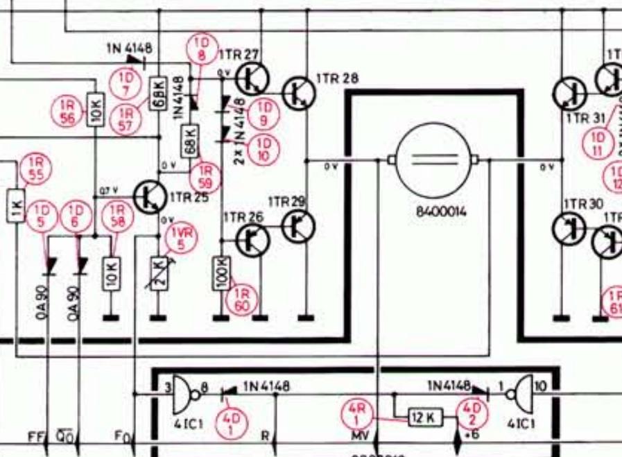
23 December 2023 at 12:05 #51195hcraig244SILVER MemberOk….time for a update, according to solderons training notes when FF is operated the collector of 1TR25 should go high (approx 22v) I was getting closer to 14v at this point….still good.

Also said voltage is fed to the Base of 1TR27…still good…and therafter to the Base of 1TR28 thus causing the motor to rotate in the forward direction…..the 14v was not getting out of 1TR28…..so no rotation.
23 December 2023 at 14:11 #51196hcraig244SILVER MemberRemoved 1TR28 and it tested fine! went ahead and tested all 1TR27/1RT26/1TR29…..all proved good…..put them all back and powered up and needless to say everything worked perfectly…..dry solder joint somewhere? temperamental transistor?
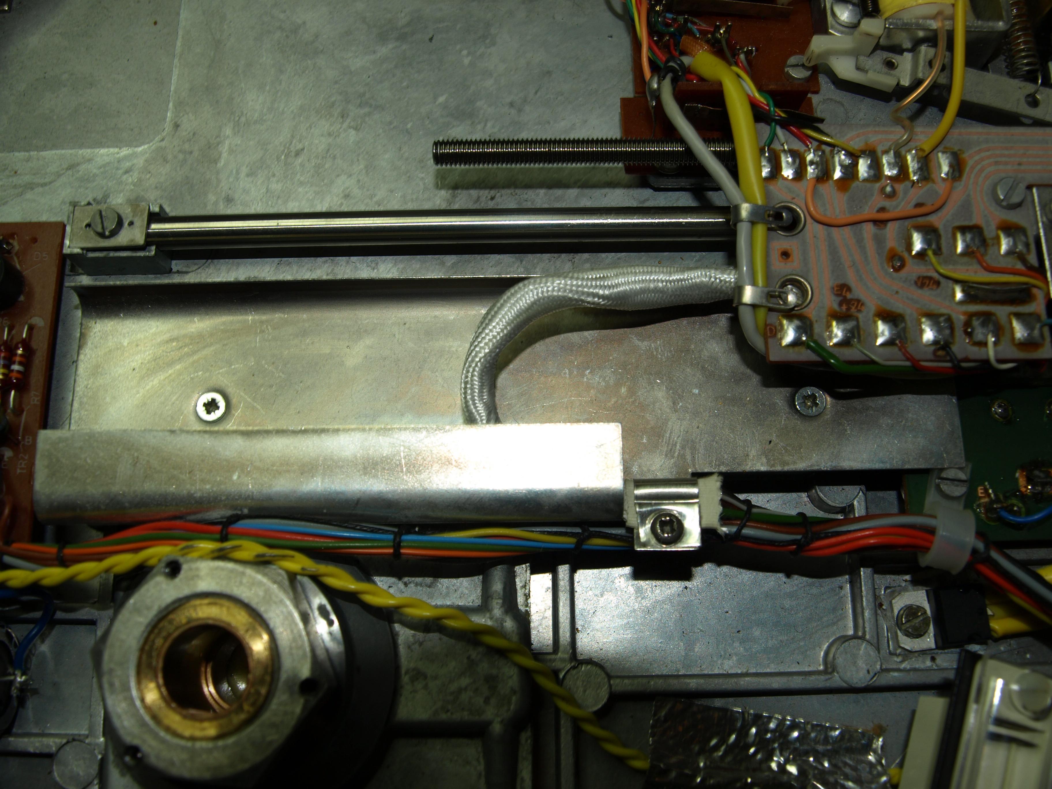
23 December 2023 at 14:24 #51197hcraig244SILVER Memberduring testing I found that when the tone arm approached the ES position it was slowing down considerably, when moving forward slowly by nudging the tone arm by small increments to simulate a record on the deck, and more often than not actually stopping short.
I noticed that the drive motor was still running and the belt was slipping….watching this a couple of times i spotted this..the cable containment sock was all twisted and lumpy and the carriage was fouling on it at the end of its travel…
Tht
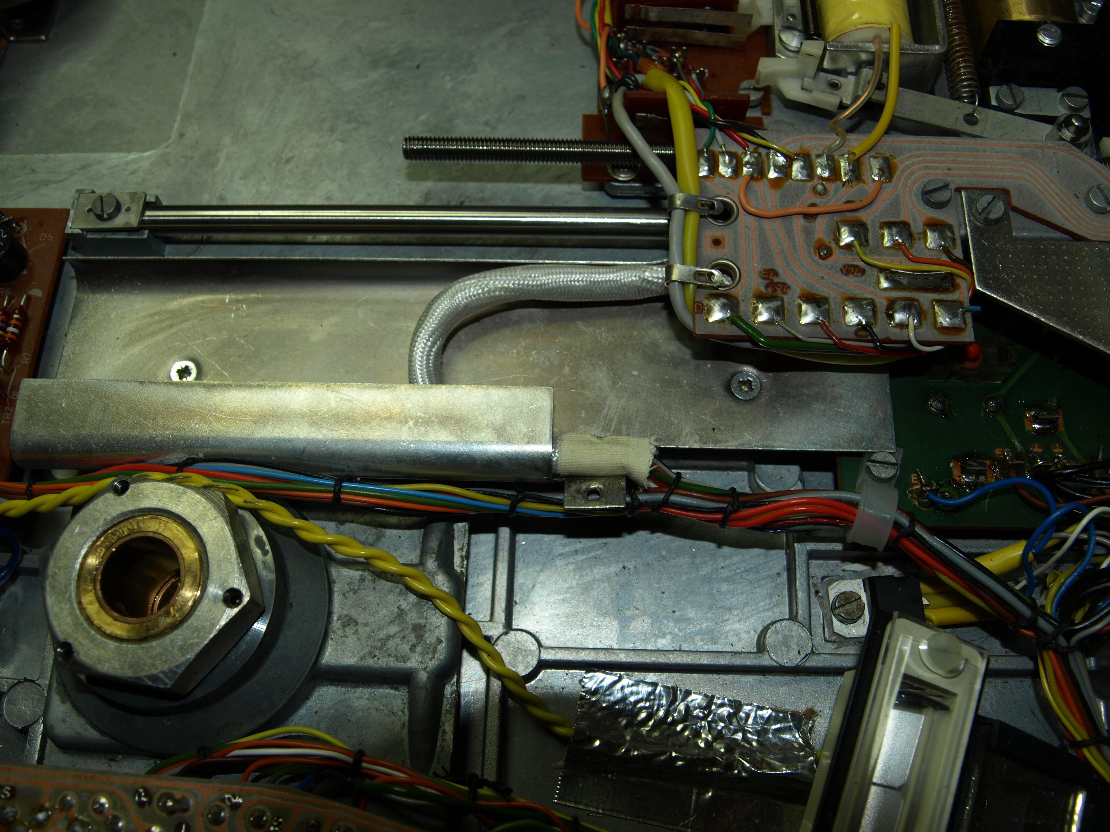
 23 December 2023 at 14:27 #51198hcraig244SILVER Member
Unclamped the sock and rotated it to remove the kinks…..this is much happier now, never seen this before……will re secure the clamp and look to replace the trimmers.
30 December 2023 at 14:25 #51199hcraig244SILVER MemberGot around to replacing the skeleton trimmers today, not that they where suspect in anyway just because they probably will fail at some point.
30 December 2023 at 14:29 #51200hcraig244SILVER MemberAnd had a dig around in my box of miscellaneous odds and ends and located some machine screws to fix the PCB in place.
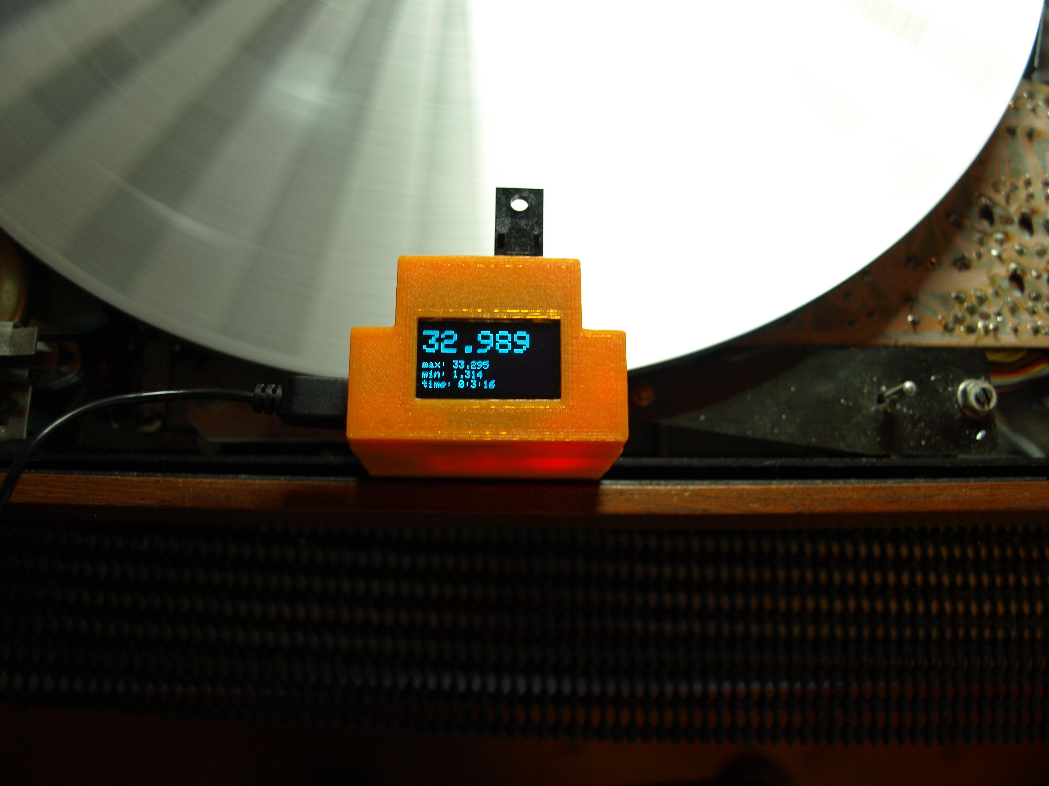
30 December 2023 at 14:46 #51201hcraig244SILVER MemberJust need to do some adjustments following the trimmer replacements…I don’t expect them to be far away as I measured across the relevant legs of each one and set the new trimmers accordingly but doesn’t hurt to check……used Rudi’s digital tachometer I purchased for the very purpose…..seems a shame not to use it. 33rpm up first and it was a little off…
-
AuthorPosts


- You must be logged in to reply to this topic.