


Home › Forums › Product Discussion & Questions › BeoGram › Question About Beogram 8002 Recapping
- This topic has 67 replies, 5 voices, and was last updated 1 year, 4 months ago by
 marcham.
-
AuthorPosts
-
30 September 2024 at 07:53 #59617
 marchamBRONZE Member
Hey all, I just got in a kit to replace all the caps in the 8002.
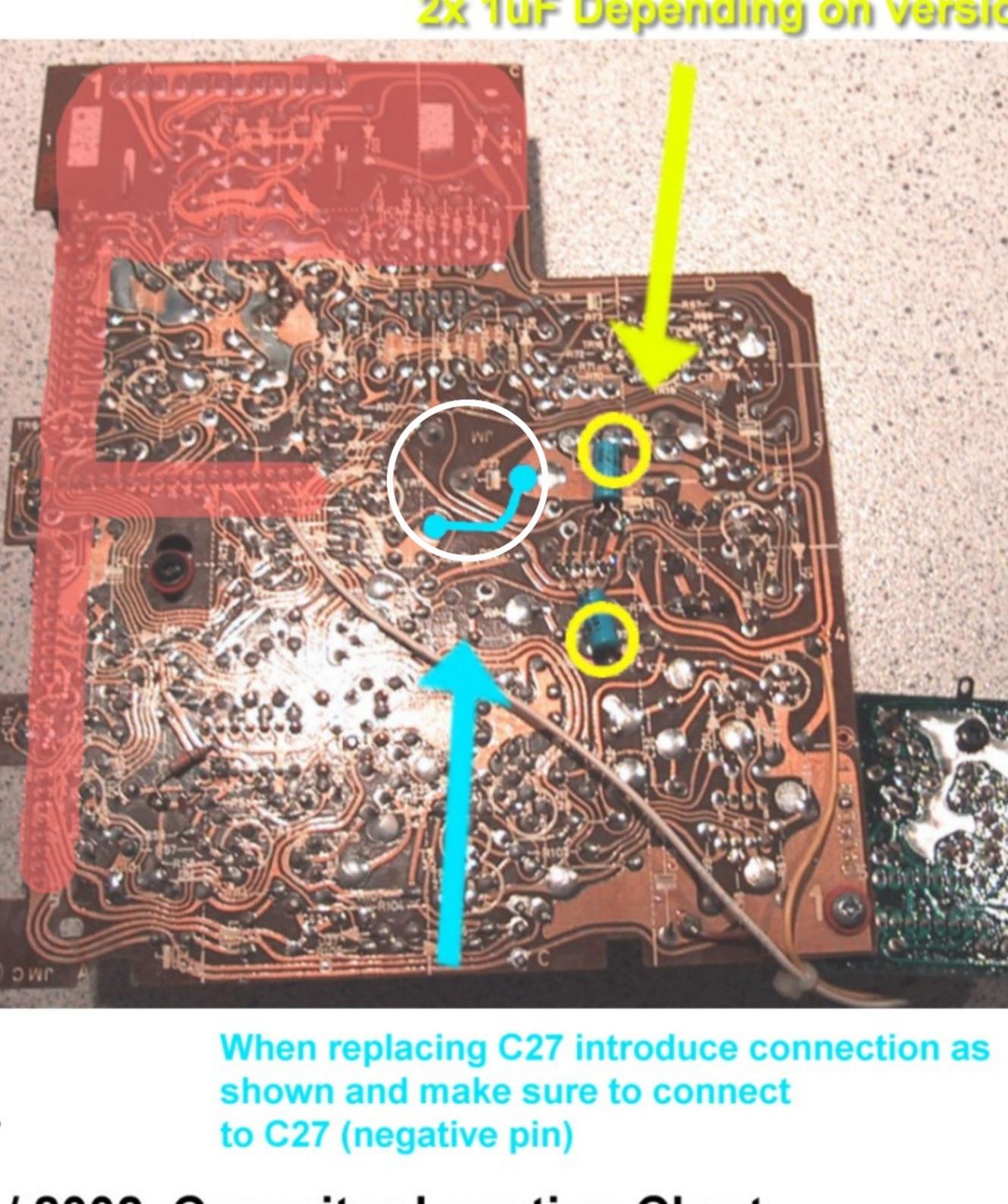
I’m a bit confused about the large cap on the board with its four legs. The kit I purchased included the instructions I’ve shared below, but for me the one sentence note isn’t clear enough on how the new capacitor should be installed.
Is it correct to assume that between the two points connected with a blue line, I should install a wire? Then, install the cap in the two remaining holes (old center hole and the top hole)? If this is correct, should the positive leg be in the center hole? I thought that’s how the old cap was installed but these instructions seem to say that the negative leg goes there.
Thanks for any clarificstion!

Location: Pennsylvania, USA
Favourite Product: Beogram 3000
Signature: - Michael Archambault
My B&O Icons:
 30 September 2024 at 14:02 #59620GlitchBRONZE Member
Is it correct to assume that between the two points connected with a blue line, I should install a wire? Then, install the cap in the two remaining holes (old center hole and the top hole)? If this is correct, should the positive leg be in the center hole? I thought that’s how the old cap was installed but these instructions seem to say that the negative leg goes there
The way that I usually do this is to install the positive lead into the center hole and the negative lead into one of the (blue) holes that needs the jumper. The negative lead should be long enough to bend over to the other (blue) hole to act like a jumper. Just make sure it doesn’t short anywhere on the backside of the circuit board.
Glitch
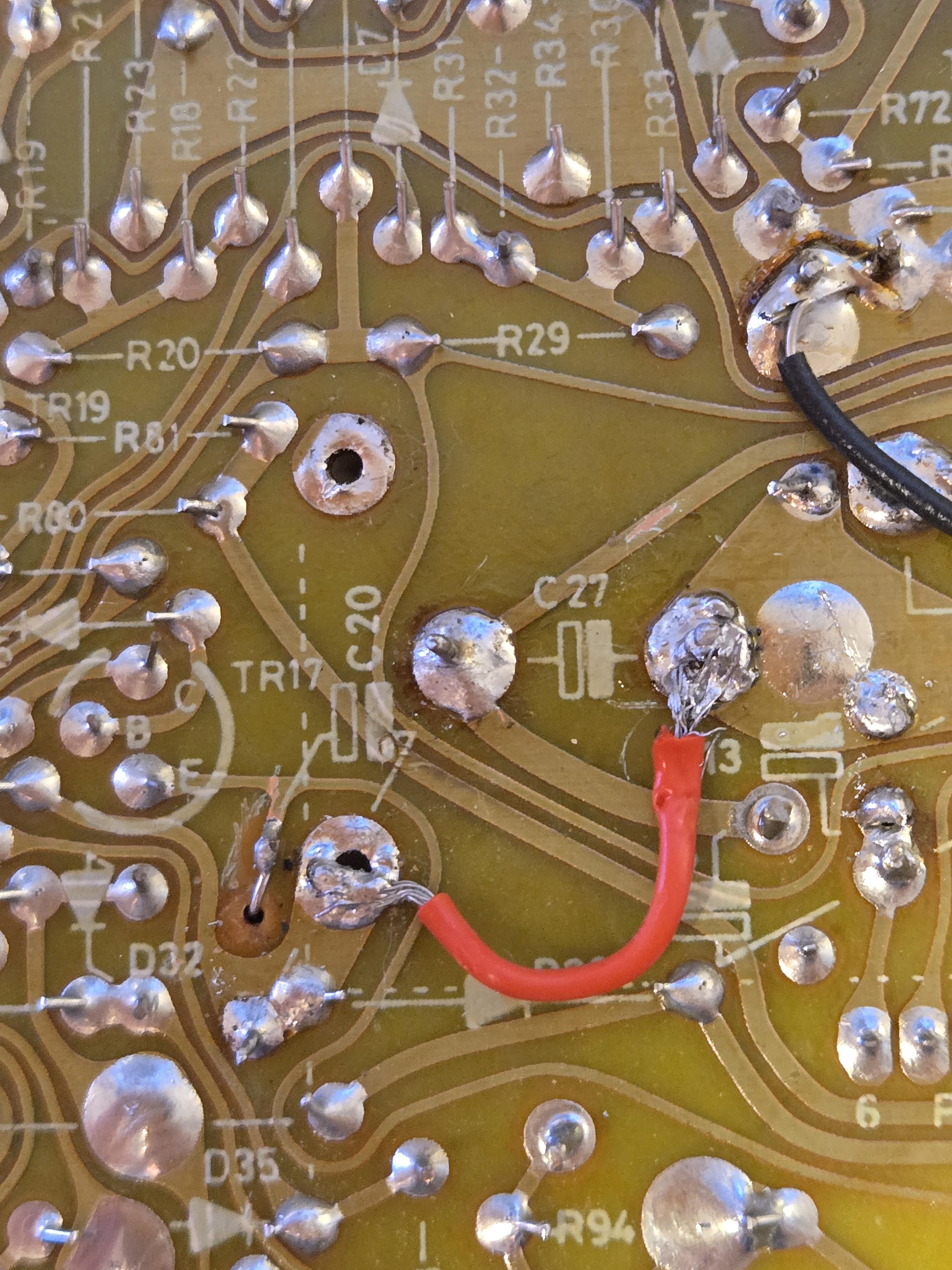
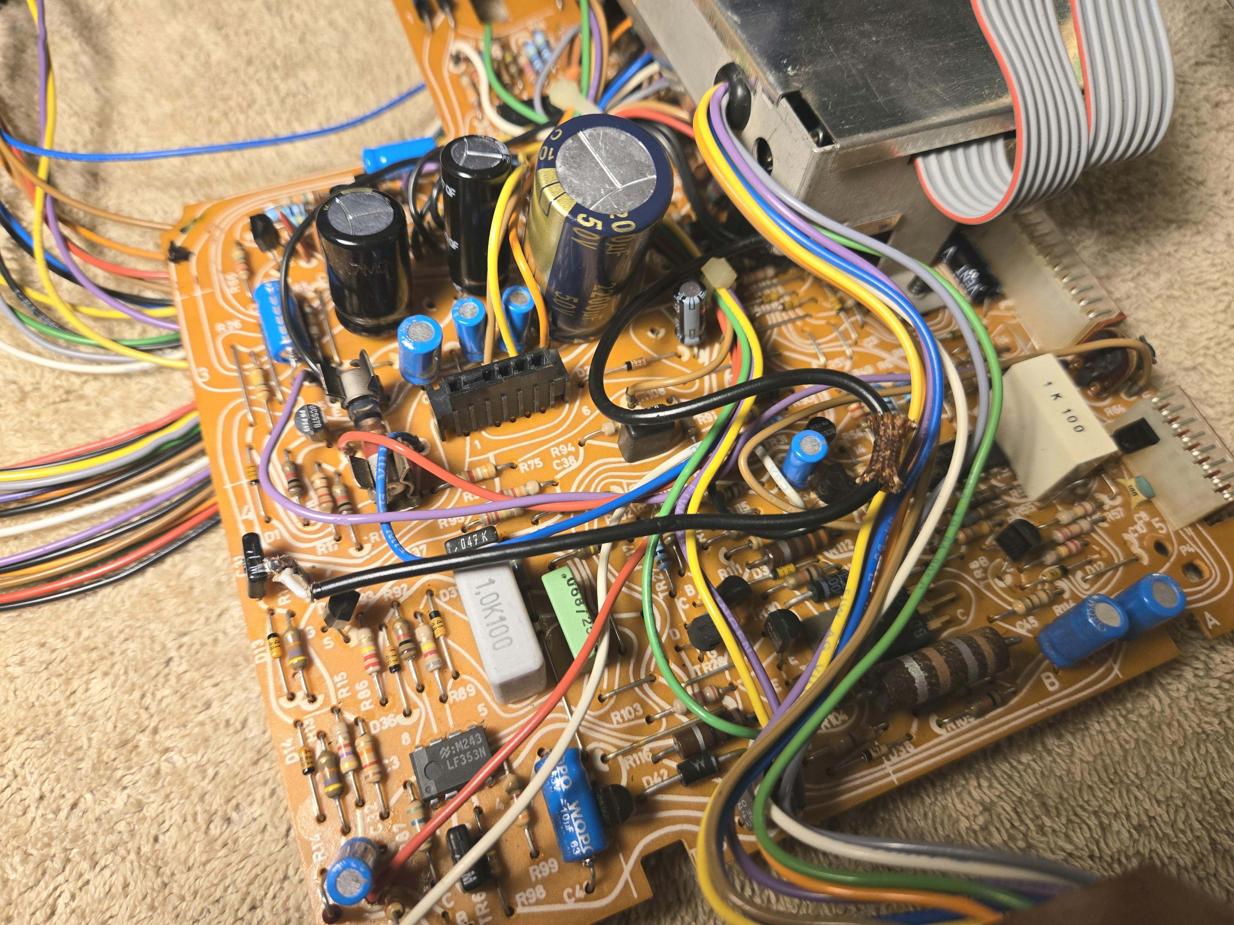
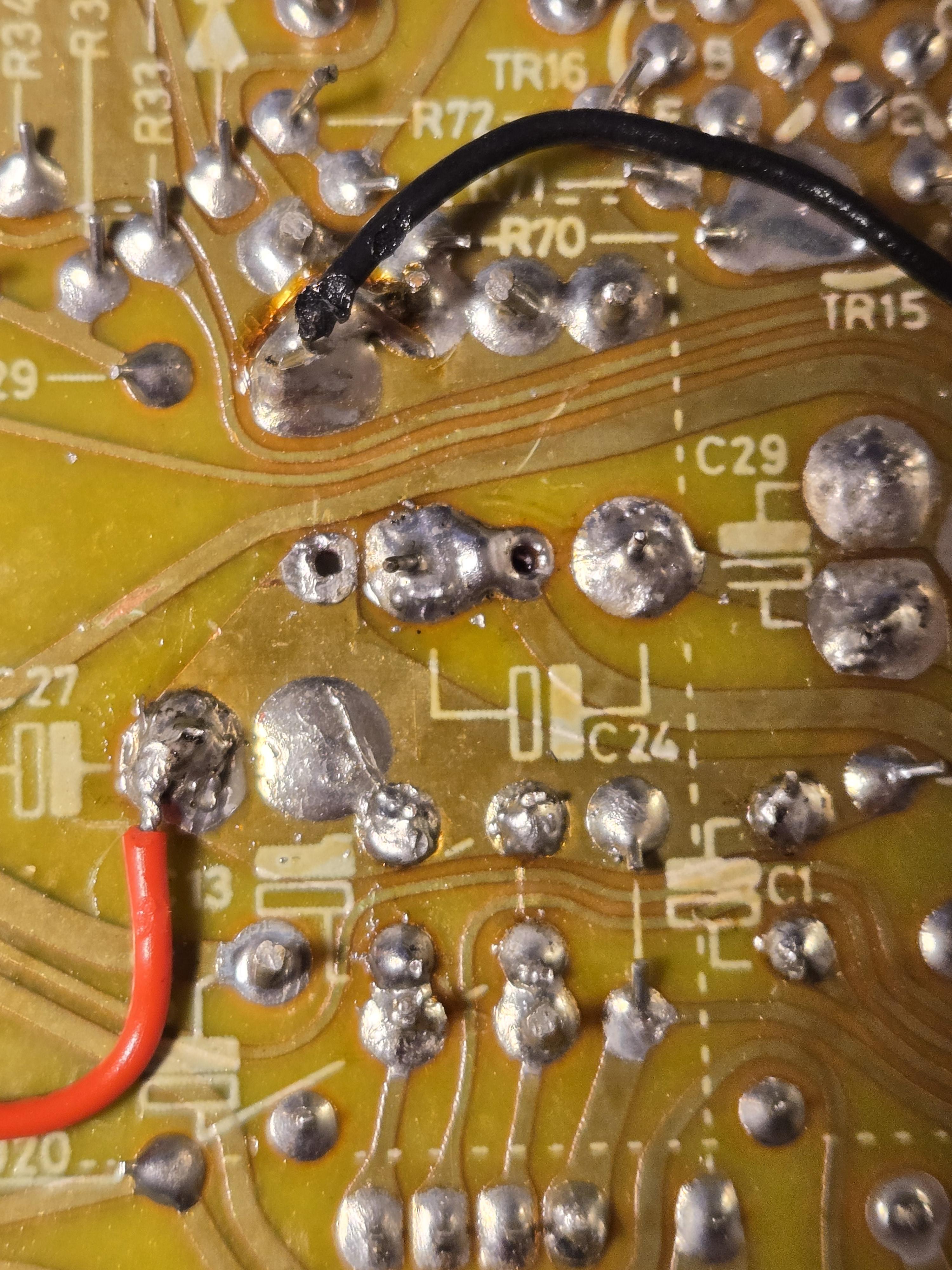
30 September 2024 at 23:36 #59644marchamBRONZE MemberThe way that I usually do this is to install the positive lead into the center hole and the negative lead into one of the (blue) holes that needs the jumper. The negative lead should be long enough to bend over to the other (blue) hole to act like a jumper. Just make sure it doesn’t short anywhere on the backside of the circuit board. GlitchThanks, Glitch. Apparently I installed it the wrong way the first time. I’ve included a photo; let me know if that’s what you were communicating. Ignore the bad looking solder job—it all holds up firm and has continuity. I’ll visually touch it up when I’m done. Unfortunately, now the machine isn’t giving me anything. When I first got it, it turned on, moved the tone arm half an inch, then shut off again. Told it needed new caps.Now, not even getting a standby light. Checked all the caps to make sure they’re in the correct orientation and there are no solder bridges, etc. All the fuses also look good.Primary concern are the connectors that are bare metal into black slots (like the two running from the CPU PCB to the main board). They fit into their respective spots and are pushed all the way down but aren’t really secure and slide right out if given the chance.Any thoughts? Thanks for any help!
Location: Pennsylvania, USA
Favourite Product: Beogram 3000
Signature: - Michael Archambault
My B&O Icons:
1 October 2024 at 07:22 #59650marchamBRONZE MemberFollowing up with some additional information.
Found a post on Beolover about checking the power when the 8002 shows no sign of life. They recommended checking the 5V regulator first, but I’m not sure on how to measure it.
Any detailed instructions are welcome on testing the 5v regulator or the power in general. I have basic soldering skills and know how to probe with a multimeter, but my knowledge ends there.

Location: Pennsylvania, USA
Favourite Product: Beogram 3000
Signature: - Michael Archambault
My B&O Icons:
1 October 2024 at 16:01 #59655GlitchBRONZE MemberI’ve included a photo; let me know if that’s what you were communicating.
How you installed C27 is correct now.
Beogram 800X’s are usually straightforward to repair. Replacing bad fuses and fixing cracked solder joints is usually the first step. Then check the important voltages (i.e. power supplies). Replace any capacitors related to improper voltages. This will usually get the machine running again or at least showing significant signs of life.
Getting specific advice on why your Beogram will no longer power on will be difficult. Advice like you found on Beolover’s site are usually intended for machines that have died naturally.
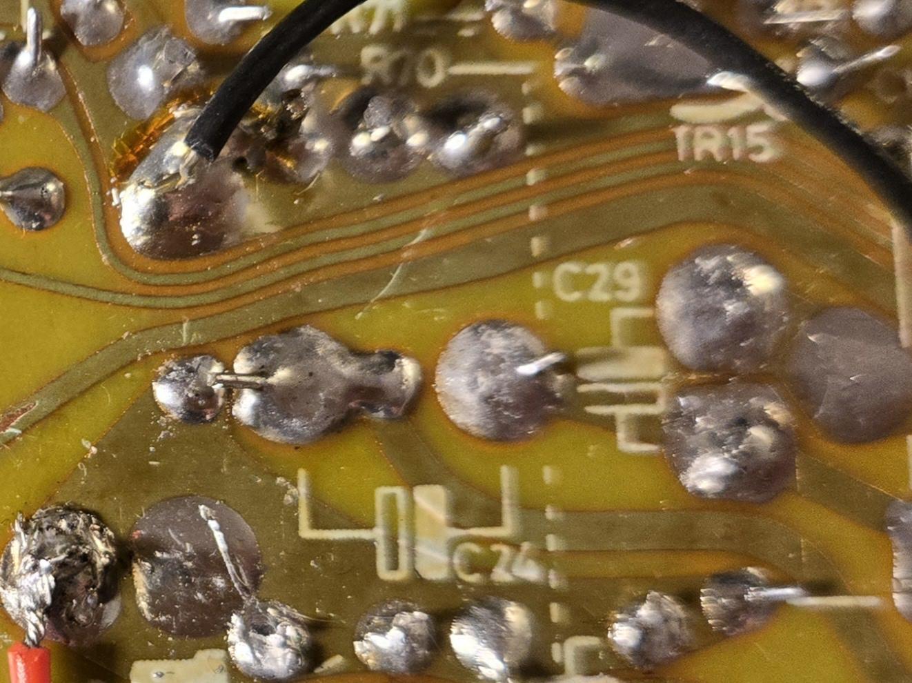
Since your machine had signs of life before the recap, I would concentrate on fixing cracked solder joints (usually on the cable connectors) and checking your work. I don’t want to sound harsh, but the soldering in the pictures could use significant improvement. It might be worthwhile to buy a “soldering practice kit” to up your game before attempting to do further repairs. Build the kit, see that it works, remove all the parts, then rebuild it again. Watch some YouTube videos to get tips. I noticed the missing solder pad for C20. This is usually an indication of someone that is struggling. It is likely that your machine can be salvaged, but the more damage that you inflict on the machine with bad soldering techniques, the harder that it will be to repair. Pretty solder joints aren’t just for show, there is a structural aspect to it that ensures long term connectivity and reliability.
Once again, I hope you take my advice in the spirit of giving you the best chance at a successful repair.
Glitch
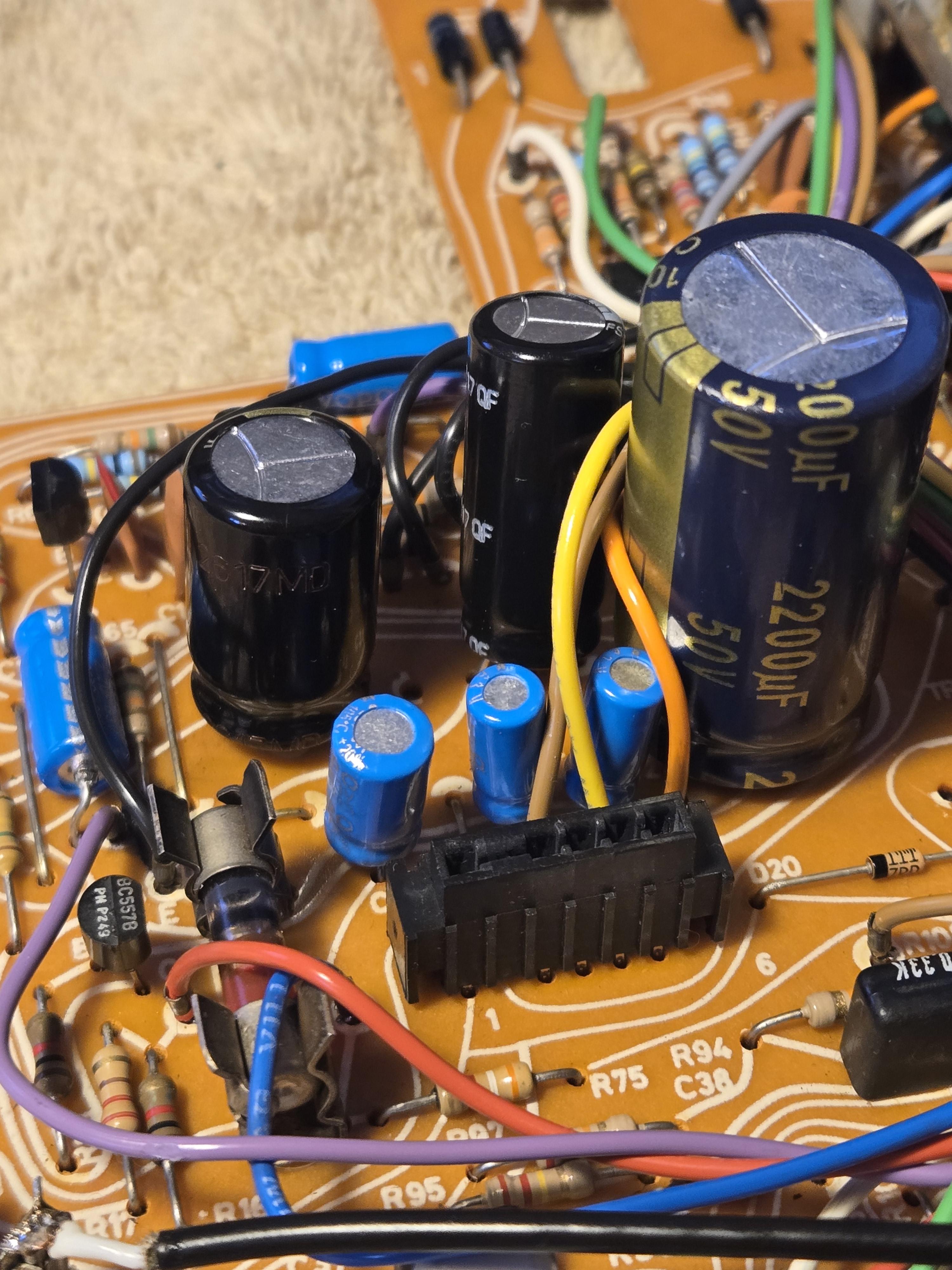
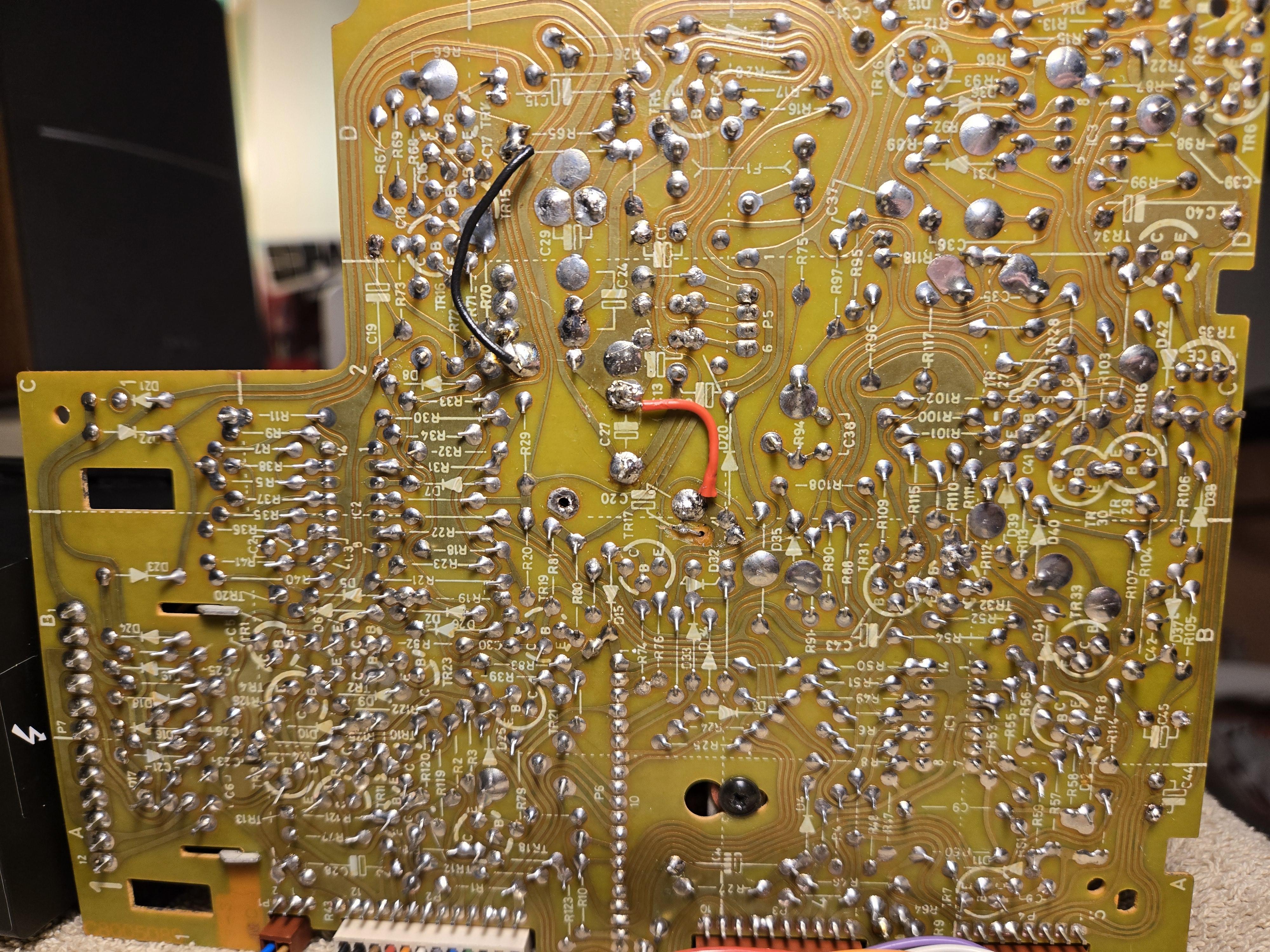
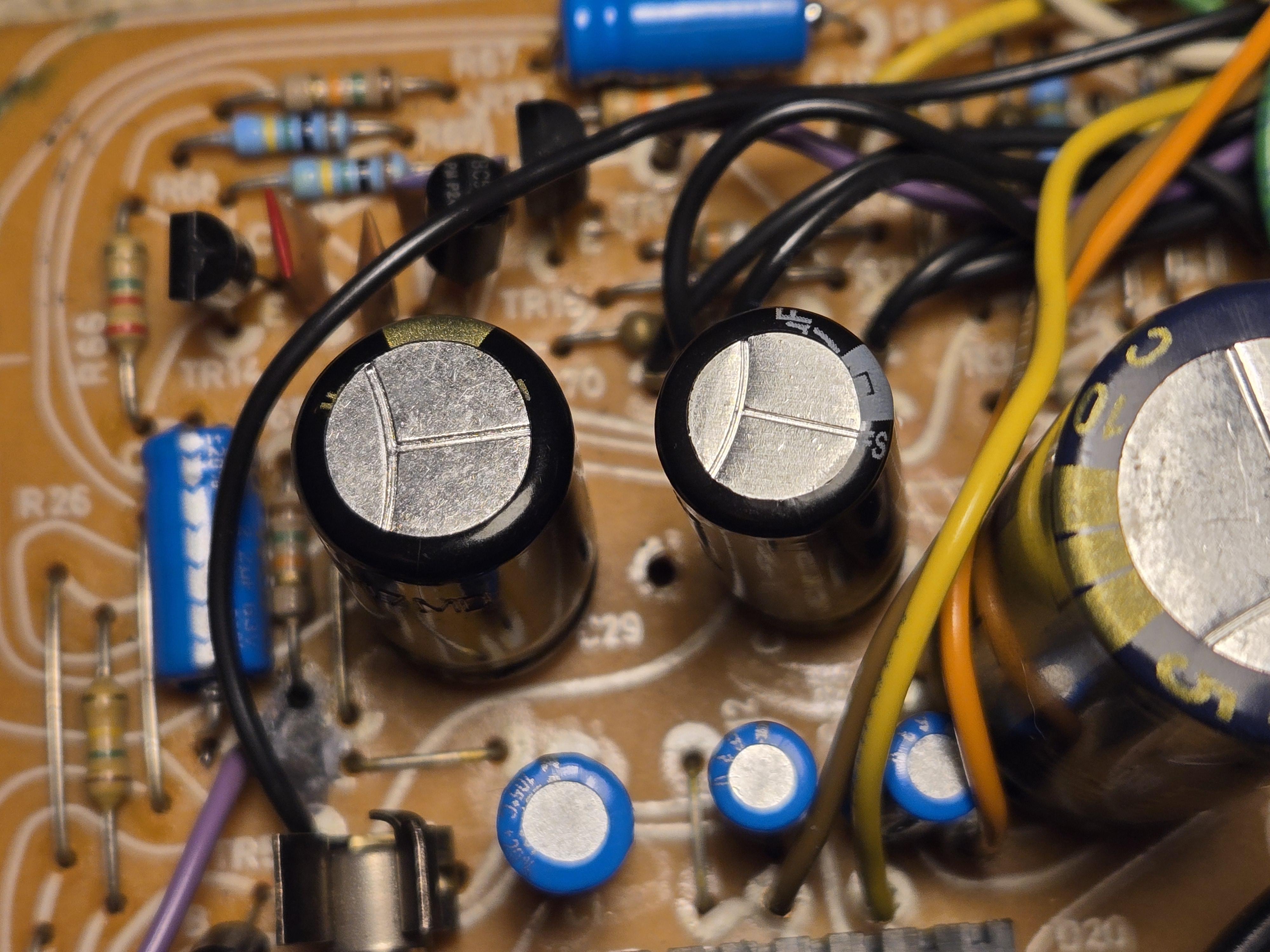
2 October 2024 at 02:44 #59673marchamBRONZE MemberI appreciate the advice, Glitch. I left the comment about not worrying about the soldering in my photo because I had an issue with my solder station and consistent temperatures. To show, I’ve retouched the board now that the station problem is resolved. I’ve also included photos of my recap job. Is it perfect? No, not at all, and I will keep practicing (I struggled a bit with the wire not being though-the-hole)! But it’s nowhere as bad as you might have thought initially. 🙂
Going back to the issue, I triple-checked my work: I looked for potential cracks, made sure the caps were installed with the correct polarity, and used a meter to test for continuity to ensure solid connections to points down the circuit— everything looked good. I also went through reflowing joints for all the major connectors. I think a component may have failed from excessive heat (I mentioned my solder station issue before), and I wonder if a cap has gone.
My plan at this point is to ensure power is flowing correctly, and I’ve been told that it starts with the 5V regulator. Any assistance or detailed steps to ensure the PSU delivers voltage and electricity flows would be welcome. I had to move the metal shield on the transistor I pointed out at one point, and I wanted to ensure the component is now working.
Location: Pennsylvania, USA
Favourite Product: Beogram 3000
Signature: - Michael Archambault
My B&O Icons:
2 October 2024 at 13:02 #59690GlitchBRONZE MemberI think a component may have failed from excessive heat (I mentioned my solder station issue before), and I wonder if a cap has gone.
You are correct to be worried about excessive heat. Capacitors are more tolerant of overheating than transistors, diodes, or ICs. The solder pads on the circuit board are also sensitive to being overheated. The big issue with the pads is that the effect is cumulative. Every removal/replacement of a component puts the pad at risk. This the main reason that I suggested practice. Being able to solder and desolder quickly and cleanly is the key to avoiding damage.
For the voltage debugging… Get the schematic, start at the transformers, and check the voltages from there. The power supply circuits are pretty straightforward. Be aware that there are a mixture of AC and DC voltages.
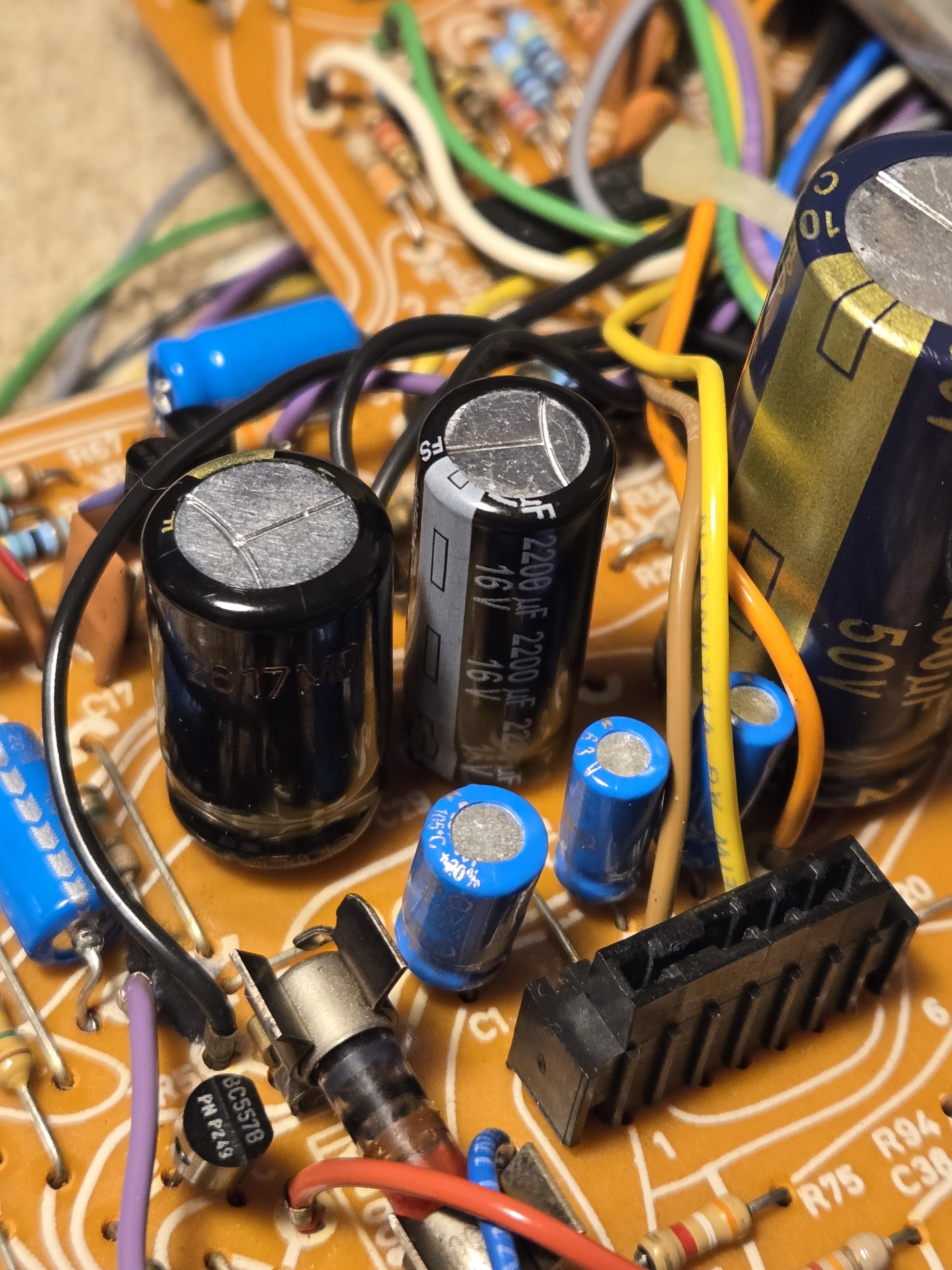
Are you sure that C24 is installed correctly? There are multiple sets of holes for that part and the capacitor polarity marking on the circuit board could be misinterpreted depending on which set that you used.
Glitch
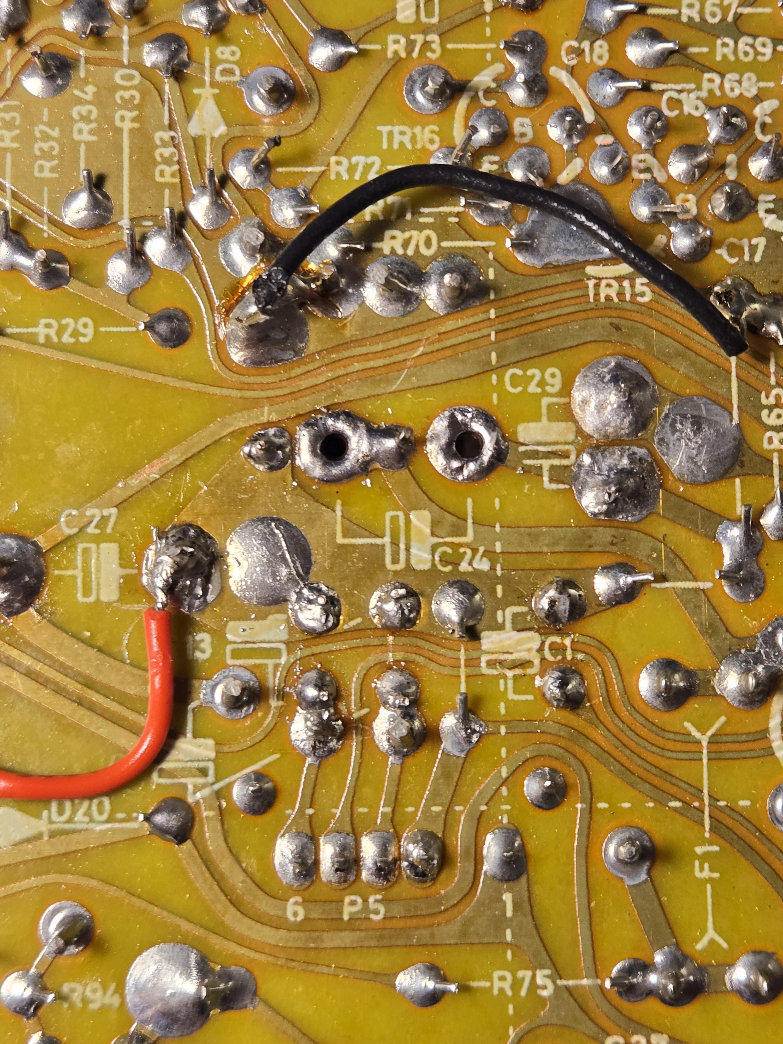
3 October 2024 at 01:31 #59711marchamBRONZE MemberHey Glitch, nice eye there! I’ve gone ahead and redone C24 as shown below. Another oddity that I noticed with this cap is that the board diagram shows reversed polarity compared to how the original was installed. Both the original cap and any repair work I have seen the other way. Thoughts?

Location: Pennsylvania, USA
Favourite Product: Beogram 3000
Signature: - Michael Archambault
My B&O Icons:
3 October 2024 at 03:12 #59713GlitchBRONZE MemberAnother oddity that I noticed with this cap is that the board diagram shows reversed polarity compared to how the original was installed.
I don’t recall the exact details of this, but the “apparent polarity” of the capacitor (as viewed from the top of the board) changes depending on whether one uses the wide or narrow mounting holes. Most of the time, one can simply match the orientation of the stripe on the new part to that of the old part (as viewed from the top of the board). However, this board has an unusual arrangement that needs special care.
The negative pad of the primary hole is connected to negative pad of the alternate hole by a trace that snakes around and a jumper wire on the top of the board. It is hard to explain in plain text. The important thing to note is that the polarity marking on the back of the board is correct and the capacitor should be installed to match.
Glitch
3 October 2024 at 03:36 #59714marchamBRONZE MemberThanks, Glitch.
I tried both methods shown below, and neither worked. I’ve left it in the ‘A’ configuration that you suggested.
Here is the ‘A’ configuration that you suggested.


Here is the ‘B’ configuration I see for other repairs, such as Beolover.

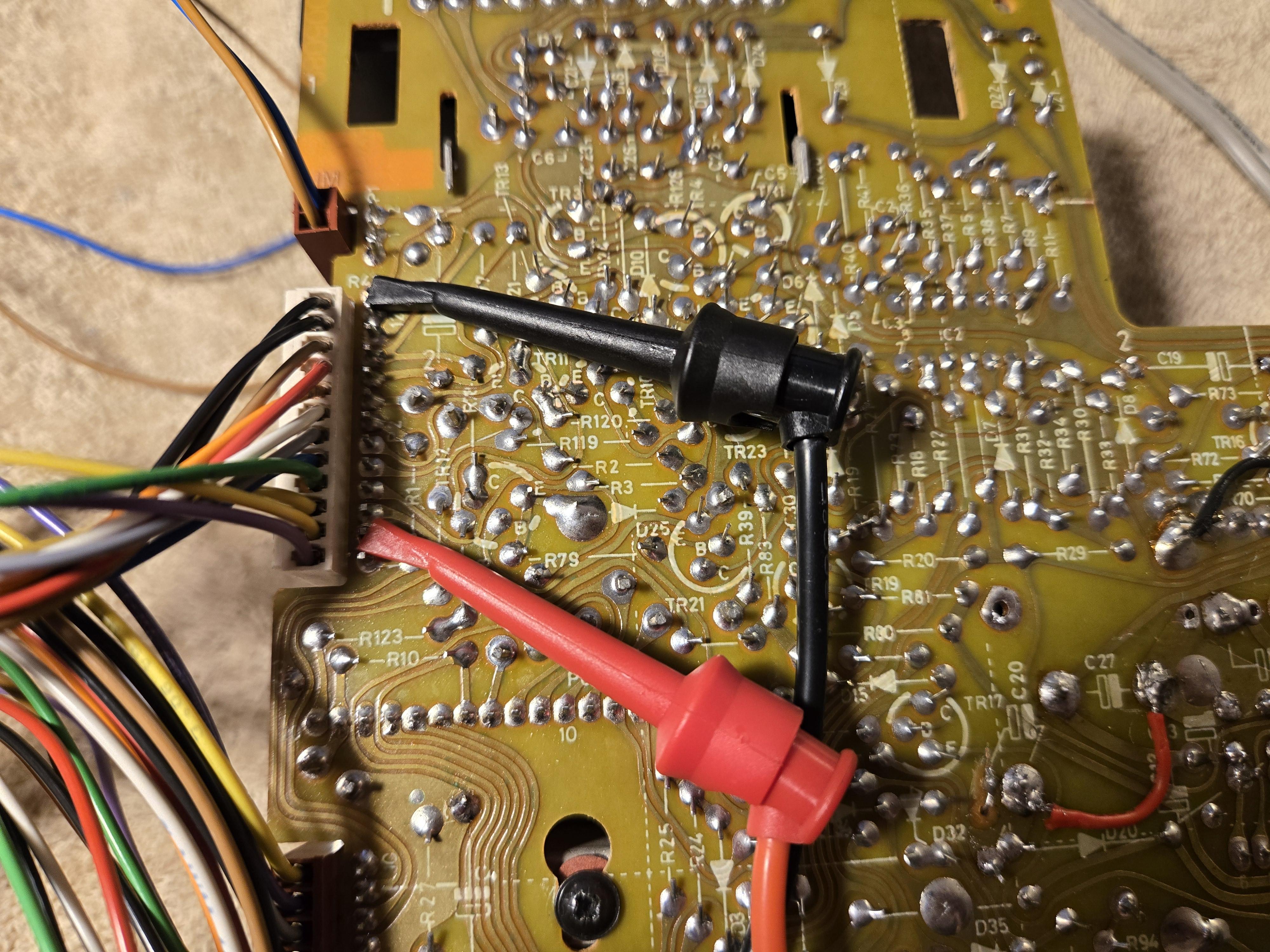
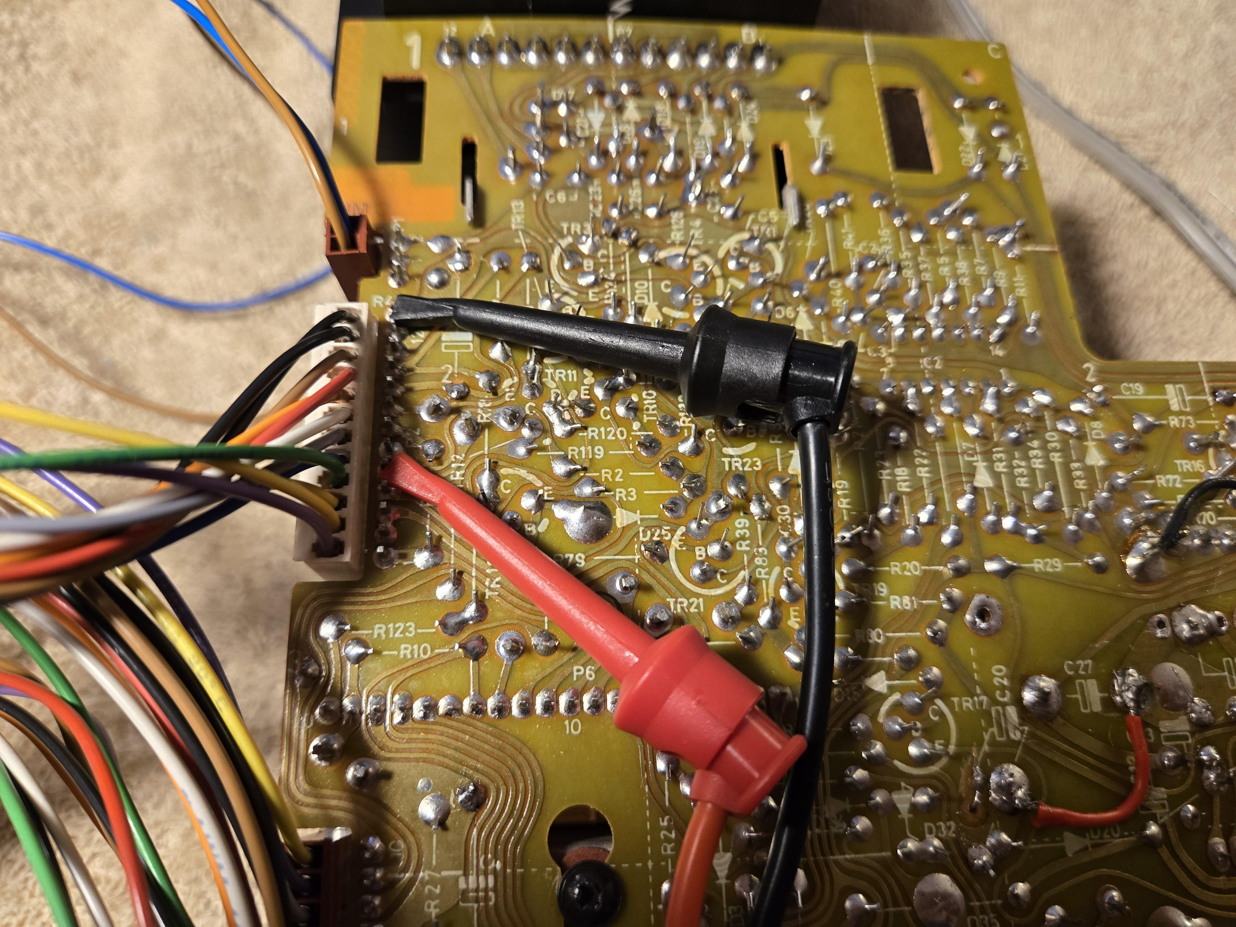
If I did want to test the power supply to ensure everything is working fine and test the 5V regulator, would you be kind enough to specify exactly where I should place my meter probes? Beolover provides a good guide for measuring across caps for the power supply, but I can’t see from his photo which legs of the transistor to attach to for 5V.
Thanks again for your help and time.
Location: Pennsylvania, USA
Favourite Product: Beogram 3000
Signature: - Michael Archambault
My B&O Icons:
3 October 2024 at 04:17 #59715GlitchBRONZE MemberAs far as the polarity for C24 goes… One way should work normally, the other will likely make smoke. It should be obvious which way you have ;-).
edit: Upon closer inspection of your pictures, it appears that two configurations shown are electrically identical since you rotated the capacitor 180 degrees when you shifted it in the mounting holes. The same mounting hole shift without the rotation is the recipe for smoke. 😉
As far as the pins and probes goes… The 5v regulator is a standard 7805. Downloading the data sheet should give you all the info that you need. Based on the BG8002 schematic, you could also measure the input and output voltages for the regulator on connector P2-5 and P2-2, respectively.
Glitch
3 October 2024 at 06:33 #59718DillenModeratorThere are four holes provided for C24 (to allow for components with different pin spacing).
Going from C27 towards C29 they are negative, positive, positive, negative.
Note that the two negative holes are connected together through the jumper next to C1.
This can often cause confusion.Martin
3 October 2024 at 21:45 #59755To add one advisory to the excellent advice already posted, if you have put in one or more of the electrolytic caps backwards and tried to turn it on, you’ll need to check the fuses, transistors and regulators prior to that as you have effectively shorted them. This is likely why you have not made progress.
3 October 2024 at 22:11 #59756GlitchBRONZE Memberif you have put in one or more of the electrolytic caps backwards and tried to turn it on, you’ll need to check the fuses, transistors and regulators prior to that as you have effectively shorted them
Don’t forget about checking the capacitor that was installed backwards. (don’t ask me how I know) 😉
Glitch
4 October 2024 at 04:22 #59757marchamBRONZE MemberI appreciate all the advice from everyone.
The only capacitor that may have been inserted incorrectly at one time and powered up would have been C24.
When plugging everything in, I get no voltage across the following points.
Please let me know if I’m mismeasuring anything.
Thanks, all.


Location: Pennsylvania, USA
Favourite Product: Beogram 3000
Signature: - Michael Archambault
My B&O Icons:
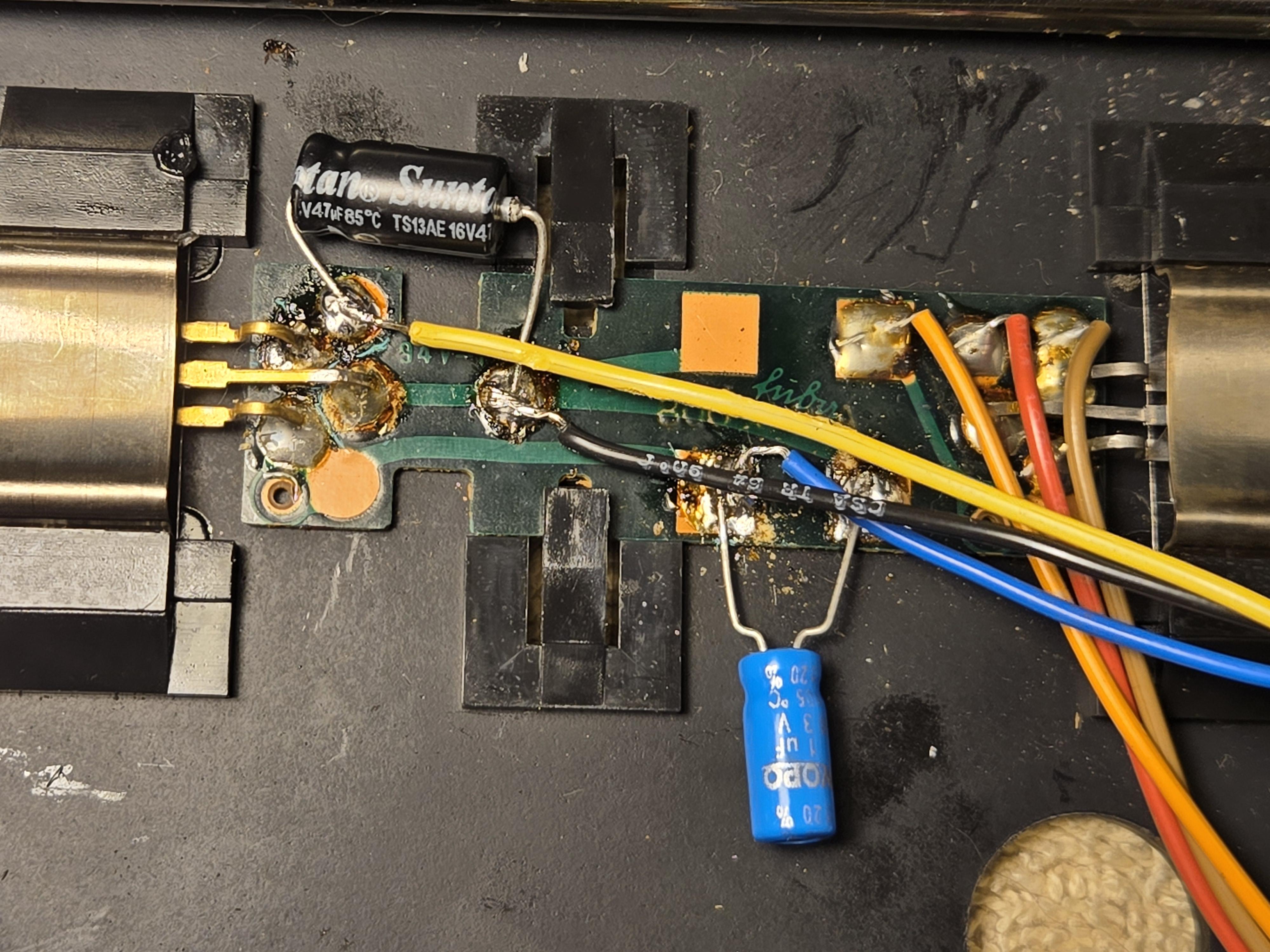
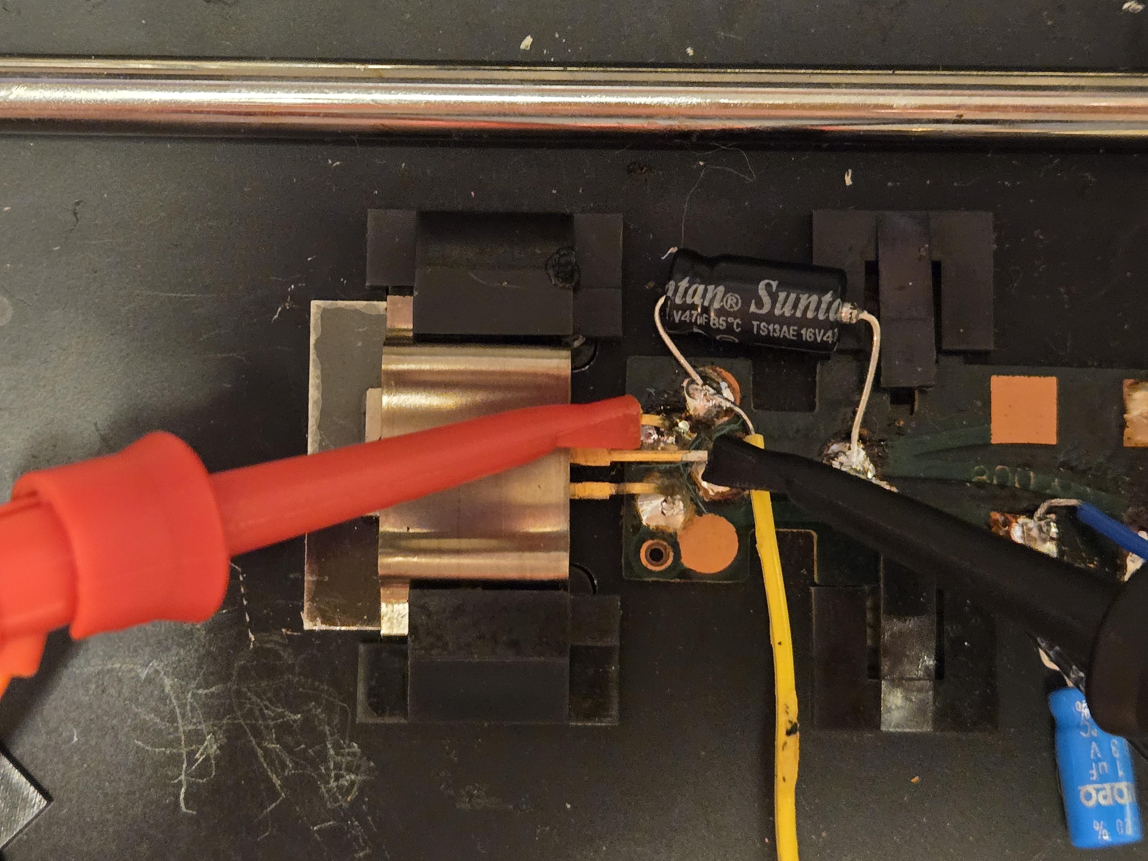
4 October 2024 at 07:52 #59775DillenModeratorJust a side note:
The 47uF axial capacitor on the subchassis must not rest on the black plastic support.
There is no room for that. The subchassis movement will be restricted by it when the Beogram is assembled.
It must be arranged like the original – down on to the metal.Martin
5 October 2024 at 03:56 #59843marchamBRONZE MemberHi, all. Potentially good update on my end. After testing around a bit, I discovered at some point the fuse in the power supply went. I’m hoping once replaced, now that all caps are in the right spot, all will be good. Although I know there is a chance there could be damage elsewhere. Here’s my current question (no pun intended):
The fuse is a time delayed 300mA 250V. This has been challenging to find, but I can order it online and pay some hefty shipping ($10 on a $1 part) for slow delivery.
Or, I can grab an easier to find time delayed 500mA 250V fuse, which is available local and cheap. Could I go the second route without causing damage? Let me know if that’s a bad option.
Thanks, all!
ps – thanks for the tip on the cap placement, Dillen!
Location: Pennsylvania, USA
Favourite Product: Beogram 3000
Signature: - Michael Archambault
My B&O Icons:
5 October 2024 at 09:28 #59851DillenModeratorI would never increase the current limit of a fuse significantly.
Sometimes you can find 315mA fuses rather than 300mA. That would be OK.Martin
6 October 2024 at 06:08 #59881marchamBRONZE MemberThanks for the help and tips everyone, I really appreciate it. I ended up going ahead and ordering a 300 mA slow blow fuse online, so hopefully I’ll have it in about a week. Once I pop that in, I’ll update everyone. Thanks again!
Location: Pennsylvania, USA
Favourite Product: Beogram 3000
Signature: - Michael Archambault
My B&O Icons:
7 October 2024 at 15:48 #59953GlitchBRONZE MemberAnother possibility is to try a 250mA fuse (if it is available locally and you don’t want to wait). The worst that could happen is that the new fuse blows unnecessarily. However, I can’t recall that ever happening when I’ve done this. There is usually somewhat of a “safety factor” when fuses are sized to avoid nuisance tripping.
Glitch
-
AuthorPosts


- You must be logged in to reply to this topic.