Home › Forums › Product Discussion & Questions › BeoLab › Beolab 8000 turn off after some hours
- This topic has 34 replies, 6 voices, and was last updated 1 year, 10 months ago by
 carljh.
-
AuthorPosts
-
22 January 2023 at 10:56 #43206
 carljhBRONZE Member
I have a pair of Beolab 8000 MK2 with serial number starting at 15. They are connected to a Sonos unit with a RCA cable. One got a strange error on one speaker. When I connect the 230 V power all works great and the speaker turn ON (green LED) when starting to play music. After a couple of hours it turns OFF (red LED). Now it is impossible to get it to turn ON again. Tried to change the input selector to all different positions and also to put 5v on the correct DIN connector pin to activate the speaker. Only way to fix this issue is to pull the 230v plug for about 15 seconds and put back again. Then it will work for a couple of minutes before it turns off again. If I pull the 230v plug over night it will work for several hours before it turns off again. It doesn’t make any difference if I leave it in standby mode after I have it unplugged from mains, after some hours it will not turn ON again. I guess it is something that get warm after a while and fail.
Does anyone have any idea what the fault is?
Location: Stockholm
23 January 2023 at 14:33 #43207 BRONZE Member
Hi carljh,
Interesting story you have here.
One thing upfront, BeoLab 8000 MK2 has serial number 16992475 and up. So if you have serial 15xx xxxx, it still is a MK1. Not bad, also a great speaker!
Your remark at the end makes a lot of sense. This looks a lot like overheated components that make the protection circuit switch off. Especially, since you also describe that if turned off, and you pull the plug from mains and replug it, it only stays on for a while. Seems a lot like a overheating issue. So here’s some suggestions:
- I assume you have a set of two speakers. If so, do you have the issue with both speakers or just one?
- If it is one, touch the cool ribbon part of the PSU/Amp panel (the lower part of the front panel). Do that for both speakers. Do you feel a temperature difference?
- What you can do is unscrew the PSU/Amp panel (6 torx screws) and pull it out. Be aware that on both sides there are cables and connectors that need to be unplugged before removing the PSU/AMP panel, with care! When pulling out, check if you see foam that has been disintegrating. If that is the case, you will probably find it sticking to the PCB and components. This can easily cause overheating and malfunction. (I know that from a certain serial number onwards, the foam that disintegrates has been replaced by B&O for a newer type. The old type can be recognised by the dark brown color. The newer foam type can be recognised by the white color.
Hope this helps.
Location: The Netherlands
Favourite Product: BeoSound 9000
My B&O Icons:
23 January 2023 at 15:05 #43208 carljhBRONZE Member
Thanks for the feedback KolfMAKER, appreciate it a lot.
I am a little confused with the generation terminology. I got the impression that the first generation BL8000 with a 2,5 way speaker was called MK1 and then the upgraded bass 1999 called MK2 and finally the ABL 2003 called MK3 but I am not sure.
Anyhow, back to your questions:
- I got two speakers and one works perfect and one has this error.
- Smart proposal! I will check if I can feel any temperature difference this evening.
- I have removed the PCU/AMP module and the speaker got the newer white foam. It is possible that some changed this because I just bought the speakers and don’t know the history. I can’t see any foam remainings on the PCB, it look clean as new.
I have downloaded the circuit diagram and got a multimeter and soldering iron but don’t know where to start looking unfortunately. Any help is welcome.
Location: Stockholm
23 January 2023 at 15:38 #43209 BRONZE Member
Mark II has serial number 1699 2475 and up, and B&O started producing them in 2002.
Production in year 1999 is serial number 13xx xxxx and up.Back yo your issue …
- So the issue is with one speaker, check.
- Yes, check if there is a temperature difference. I would assume there is one, and it should of course be with the faulty speaker.
- Good to know you checked the foam inside. If you see white foam, it might be ok. It might also be that an owner before you already made that change, but that damage by the old foam already happened.
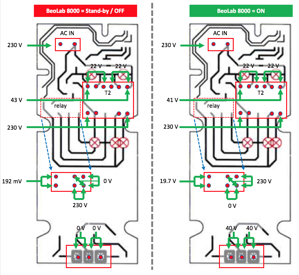
I recently also had a problem with a BeoLab 8000. Not the same as yours, but it made the speaker behave uncontrollable. By measuring the voltages on the PSU board, both in stand-by/Off an On, you can at least quickly check if they are right. In my case I found out that the T2 transformer was about to break, which it in fact also did a few days later.
So here is an overview of the PSU/PCB 01, and the voltages you should measure (in stand-by/Off and in On mode):
If all voltages are good, the issue is not the PSU section. Then you have to look into the Amplifier section.
Location: The Netherlands
Favourite Product: BeoSound 9000
My B&O Icons:
23 January 2023 at 16:12 #43210 carljhBRONZE Member
Many thanks for the advice, I will start to check the voltage levels on the PCU board.
Location: Stockholm
23 January 2023 at 16:33 #43211 BRONZE Member
Another suggestion for you, to make things easy.
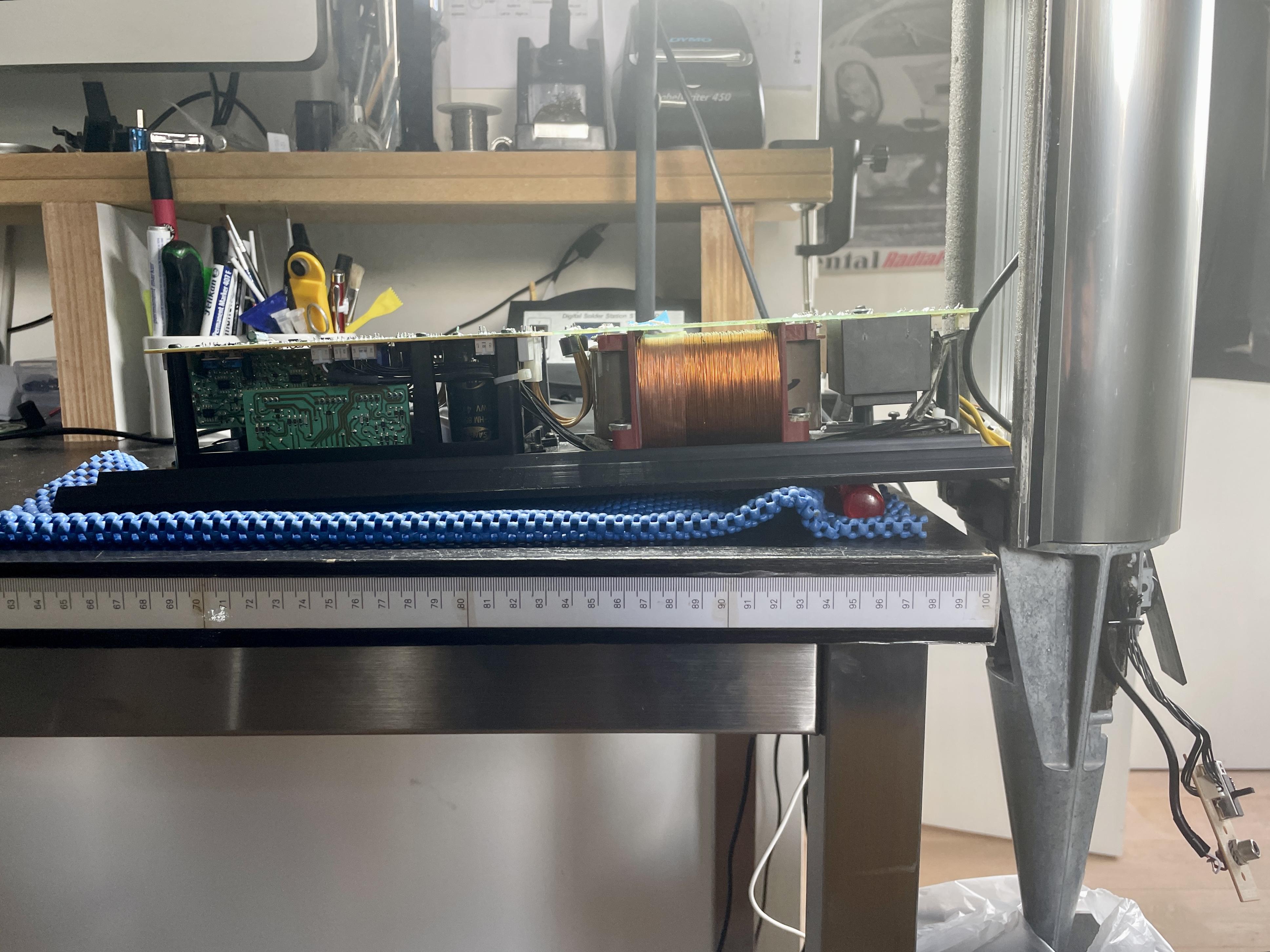
If you keep the BeoLab 8000 in an upright position, then you can more or less ‘unfold’ the lower panel with the PSU and the Amp. So to speak; ‘turn it as a hinge’. (See picture)
If you work this way, the power- and the two JST-connectors will still be connected (via the bottom of the speaker casing). So the PCB’s will be powered as normal.
But also, you will have easy access to the trace-side of the PCB to do your measurements. Because it will be face up to you.
Location: The Netherlands
Favourite Product: BeoSound 9000
My B&O Icons:
24 January 2023 at 15:50 #43212 carljhBRONZE Member
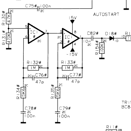
I made some more testing yesterday and realised that I connected the wrong pin in the DIN connector for the 5V power on activation signal. When the speaker get into the error stage after some hours it is possible to turn it on by 5V on pin 4 in the DIN connector. I assume this mean that the error is in the autostart circuit so I will look there, see attached picture I found in another post.
Location: Stockholm
24 January 2023 at 16:19 #43213 BRONZE Member
Ah, I did not understand that you had the 5 volt connected most of the time.
I expected that you were mainly talking about the RCA connection between Sonos and BeoLab.
Location: The Netherlands
Favourite Product: BeoSound 9000
My B&O Icons:
2 February 2023 at 15:22 #43214Prime
BRONZE MemberI made some more testing yesterday and realised that I connected the wrong pin in the DIN connector for the 5V power on activation signal. When the speaker get into the error stage after some hours it is possible to turn it on by 5V on pin 4 in the DIN connector. I assume this mean that the error is in the autostart circuit so I will look there, see attached picture I found in another post.
Did you have any luck yet? I dimsmantled everything and cleaned it. didnt find anything weird. I reassembled everything again but no luck.
I’m not sure which part I need to check, or replace to get that LINE input working again.
2 February 2023 at 15:38 #43215 carljhBRONZE Member
Reply to the KolfMaker: I started to connect the Sonos player via the RCA connectors and that worked for one speaker but not the other one. Now I have one speaker connected via the RCA connector and the other one via the DIN connector and 4,5V power supply to pin 4 in order to activate the speaker. This work but ideally I want it to work with the RCA auto start method for both speakers.
I will try to find the problem this weekend if I can find some time.
Location: Stockholm
2 February 2023 at 20:05 #43216Prime
BRONZE MemberWhat power supply do you use? The Sonos Port has an audio 12v trigger. But my Sonos Connect doesnt.
3 February 2023 at 11:59 #43217When a BL8000 fails to start after a while then most of the times this is caused by a failing NTC, autodetection or steering of the relais.
But as it responds to a trigger signal you can eliminate the NTC and steering for the relais.
So you have to look for the culprit in the autodetection. It happens regurlarly that IC1 fails.
Most of the failing components do not have visible damage. Just with measuring you will find out. For checking the IC a scope has a preference.Location: Utrecht
3 February 2023 at 16:34 #43218 carljhBRONZE Member
Thanks for information @beobuddy
I will check or replace the Ic1 and check if this sort the problem.
Location: Stockholm
11 February 2023 at 06:48 #43219 carljhBRONZE Member
I changed the IC1 OP amp circuit yesterday and now it work. The type is 4558 and this can be hard to find but there are alternatives.
Thanks @BeoBuddy for the direction.
Location: Stockholm
16 February 2023 at 13:29 #43220Prime
BRONZE Memberchanged the IC1 OP amp circuit yesterday and now it work. The type is 4558 and this can be hard to find but there are alternatives.
Where can I find the IC1 OP amp circuit? And what did you buy to replace it?
16 February 2023 at 13:35 #43221Prime
BRONZE MemberEdit: I found them. Can I replace them with these: https://www.amazon.nl/-/en/JRC4558-internal-compensation-circuit-20-piece/dp/B08F53PB7C/
Iv’e read online that these can be upgraded. Is it really needed, or is it better to just use these 4558 OP amps?
I think you mean this? Where can I find this on the board?
16 February 2023 at 14:57 #43222 carljhBRONZE Member
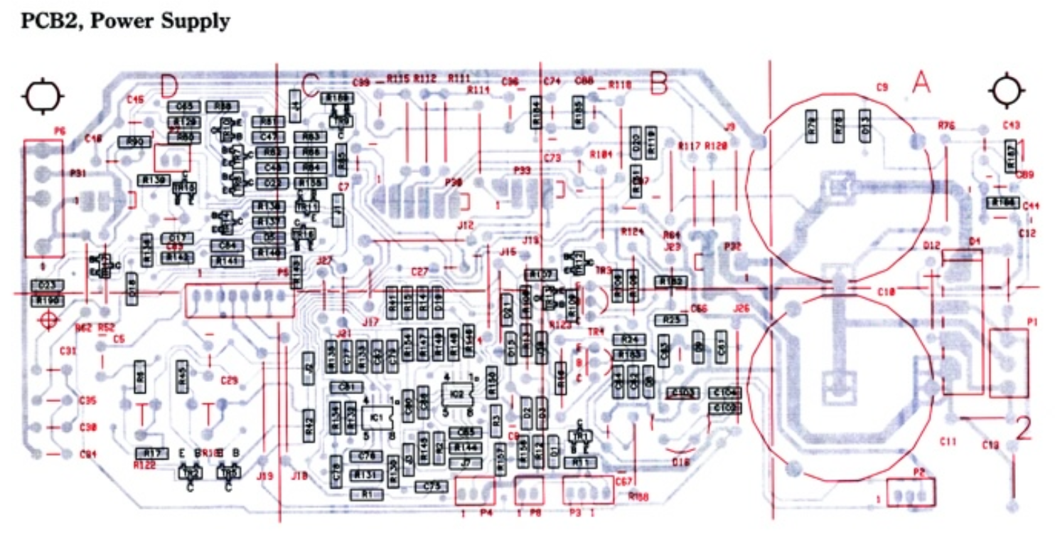
You can not use this component https://www.amazon.nl/-/en/JRC4558-internal-compensation-circuit-20-piece/dp/B08F53PB7C/ it is wrong foot. You need 4558 with a SOT8 foot for surface mounting. I used a 4558 from a broken unit I got from a B&O dealer but I think you can use this replacement component: https://www.electrokit.com/produkt/ne5532d-so-8-dubbel-op-amp/
Please find a service manual attached, you can find placement of the IC1 in this manual.
Location: Stockholm
16 February 2023 at 15:00 #43223 carljhBRONZE Member16 February 2023 at 15:56 #43224
I’ve seen boards where IC1 was “upgraded” to a OPA2134. It a rather silly exercise as IC1 only handles the signal for autodetect. The actual audio signal doesn’t pass IC1 through to the amplifiers.
Every dual opamp which works with symmetrical power supply will do the job.Location: Utrecht
17 February 2023 at 09:45 #43225Prime
BRONZE MemberIs this the correct one? https://www.reichelt.nl/nl/nl/op-amp-so-8-ne-4558-d-smd-p18790.html?&nbc=1
-
AuthorPosts
- You must be logged in to reply to this topic.


