Home › Forums › Product Discussion & Questions › BeoCord › Beocord 9000 Power Issues
- This topic has 1 reply, 1 voice, and was last updated 3 years, 5 months ago by
Glitch.
-
AuthorPosts
-
2 September 2022 at 12:45 #38795
Glitch
BRONZE MemberI have been working on a Beocord 9000 Type 4812 (late production Dolby-C model). The initial symptoms were that it would power-on (seemingly) normally, but when the play button was pressed, the tape heads would engage then disengage after a second.
I checked the 250mA fuse F1 on the power supply board (B4) and it was open. I replaced the fuse with a 250mA (fast blow) and it blew immediately when pressing play. I checked the 13v, 32v, +24v and -24v voltages on board 6. I checked the 5v, 6.2v, +15v, -15v, and -14.3v on board 4. All voltages were reasonably close to their specified values.
I pulled the tape transport module, unsoldered the leads to the motor and ran it from a bench power supply. The motor runs smooth and quiet. It draws about 90mA without the belts connected.
While I had the tape transport out of the chassis, I replaced the rubber parts and cracked idler arm (thank you beoparts-shop), and cleaned and lubricated the mechanism.
I tried running the tape mechanism outside of the chassis by connecting the 14-pin and 16-pin connectors to their respective circuit boards. Instead of replacing the fuse again, I put a multimeter in series to monitor the motor current draw. I was able to test the basic functionality of the tape mechanism. The motor currents were a bit high, but after running the FF and REW a tape end-to-end a few times, the currents came down slightly. I assume that this is due to the lubrication working itself deeper into the capstan shafts. I reinstalled the tape mechanism into its proper location, reconnected the playback and record head connectors, but left the multimeter in place since I had to order some 250mA slow-blow fuses.
This is where things started to get strange. I pressed the play button, assuming that I would be able to start testing other functionality, but the motor current spiked to about 1.2A. After spending more time studying the schematics and a doing a series of different tests, I found that I could run the tape functions as long as the playback head connector on Board6-P19 was disconnected. With the connector in place, specifically pin6, which is a ground to the tape head/transport chassis, the motor currents would rise.
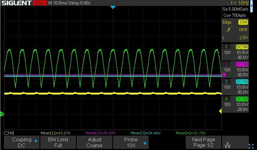
I went back and checked the various voltages under various conditions like STDBY, STOP (motor spinning some electronics powered up), and PLAY, with and without the B6-P19 connected.
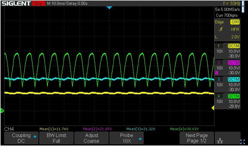
The plot below is in STDBY, the state of B6-P19 did not make much difference. Please note the “mean” values and the -24v signal is inverted to display as positive.
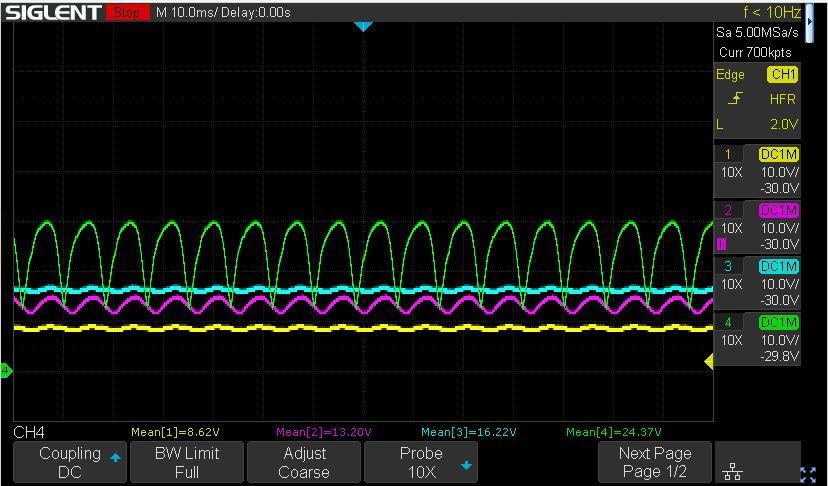
The plot below is for STOP mode with B6-P19 disconnected
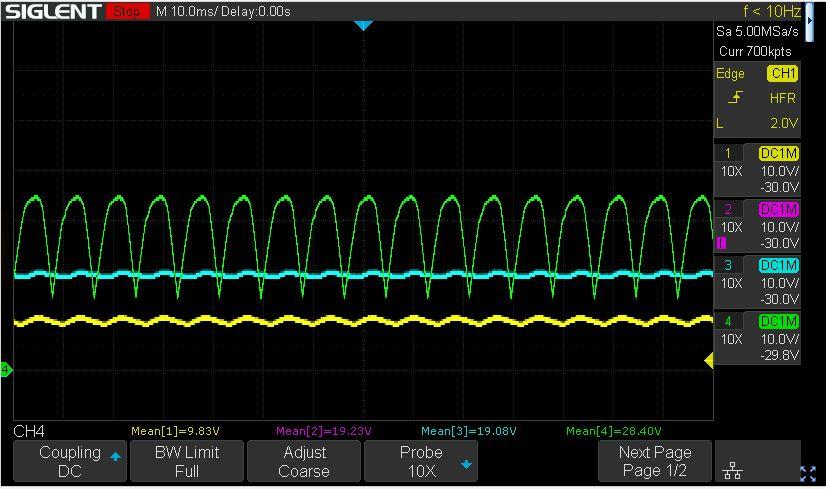
The plot below is for STOP mode with B6-P19 connected. “Something” is pulling down the voltages.
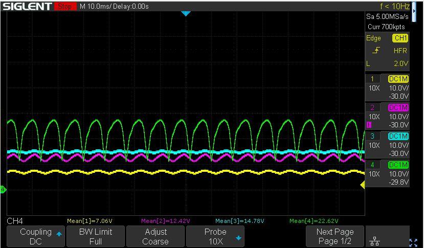
The plots below are in PLAY mode, with B6-P19 disconnected and the connected. Similar voltage drops are seen.
I believe that the motor is fine. During bench testing, the motor current is constant for a given load and does not vary much if the supply voltage is reduced. This would indicate that there is something else causing the current spike (that would normally blow the fuse).
I’ve also checked the resistance of the power and ground connections between boards and did not note anything unusual.
Now after the long-winded setup I can ask my simple question…
Does anyone have an idea of what could be pulling down the voltages? Especially considering the effect of connecting the ground on B6-P19.
I’ve studied the schematics and this seems to be defying logic. I’m hoping that someone has seen this issue before or at least can recommend common failure points that I can check next.
Thank you,
Glitch
2 September 2022 at 20:59 #38796Glitch
BRONZE MemberI found a short to the metal chassis of the tape transport. It looks like when I plugged-in B6-P19 it made a connection to the chassis via the tape head mount, to the tape head angle adjusting spring, to the tape head sliding bracket, to the transport chassis. This unlikely, and easily opened, connection likely explains why I didn’t catch the short when I checked continuity between all the pins on the 14 and 16 pin connectors and the ground pin on B6-P19.
Glitch
-
AuthorPosts
- You must be logged in to reply to this topic.


