


Home › Forums › Product Discussion & Questions › Other › LC1 Schematic and repair
- This topic has 2 replies, 3 voices, and was last updated 4 years ago by
 Homersaurus.
-
AuthorPosts
-
11 April 2022 at 09:56 #34054
 SILVER Member
Hello !
I’m glad to see that the forum is back to life !
I have recently resurrected a LC1 Light Controller that initially showed no signs of life, and have been meaning the share this repair since, but quite lacked the time. Today I fix that !
BIG WORD OF CAUTION : This device is NOT isolated from mains. That means that once plugged, the whole device is at a lethal voltage ! If you plan to work on one of these, double check that it is unplugged, and keep in mind that some of the capacitors can keep a high voltage !
SECOND WORD OF CAUTION : The device retains its settings in memory using a lithium battery, which, according the the big yellow warning label, can explode when mishandled. Avoid shorting / charging it.
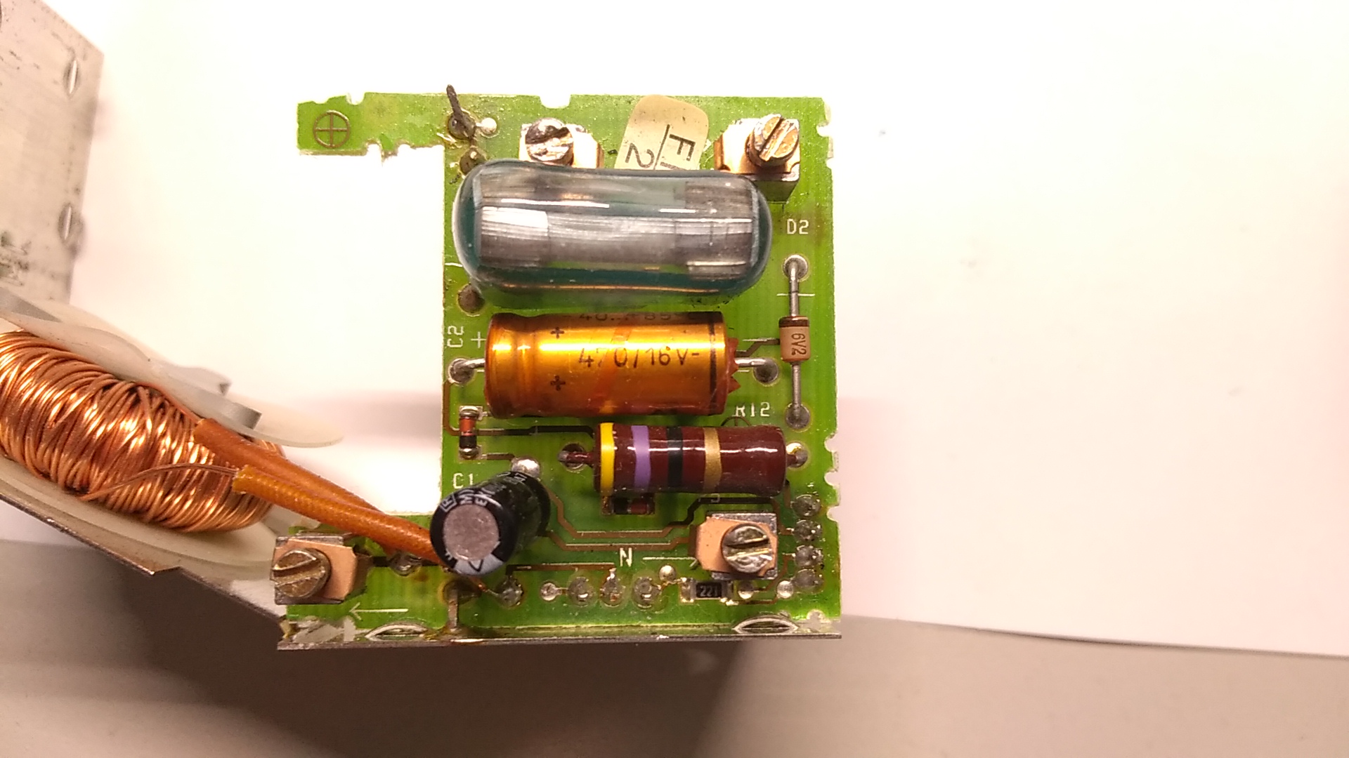
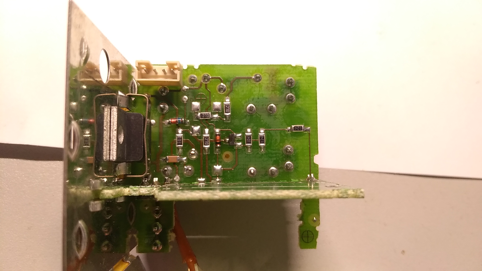
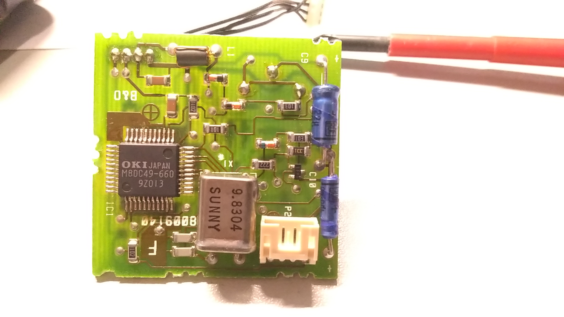
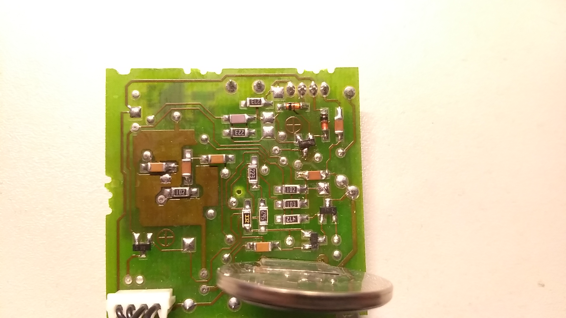
I will not spend much time on how to open it, as it is already described on this forum. Quick recap : the top IR translucent hat is force fitted to the body, and can be separated from it using a knife as a lever, and some patience. Then, one screw in the bottom area should be removed to allow the whole electronic bloc to slide through the top aperture. The “CPU” pcb is connected via 2 4-pins connectors, and can be slid out of the assembly, after bending the small metal tab locking it in position. Here are pictures of the “power” PCB and the “cpu” PCB. I have no picture of the top PCB, as its top side is hidden behind a metallic shield.

It seems that no schematic was available for this device, so my initial effort went toward drawing its schematic, which you can find here : https://pila.fr/wordpress/wp-content/uploads/2022/04/BO_LightControl1.pdf
The name of the components on the schematic maps the PCB silkscreen for the few components that have their name on the silkscreen. The others and named randomly.
Be aware that is is incomplete, as I had no interest in studying the top PCB that includes the IR receiver, nor did I take time to see on which IO of the MCU each signal goes.
It is a quite simple device, very similar to your usual halogen dimmer, but with the dimming controlled by a M80C49 CPU instead of a dumb potentiometer.
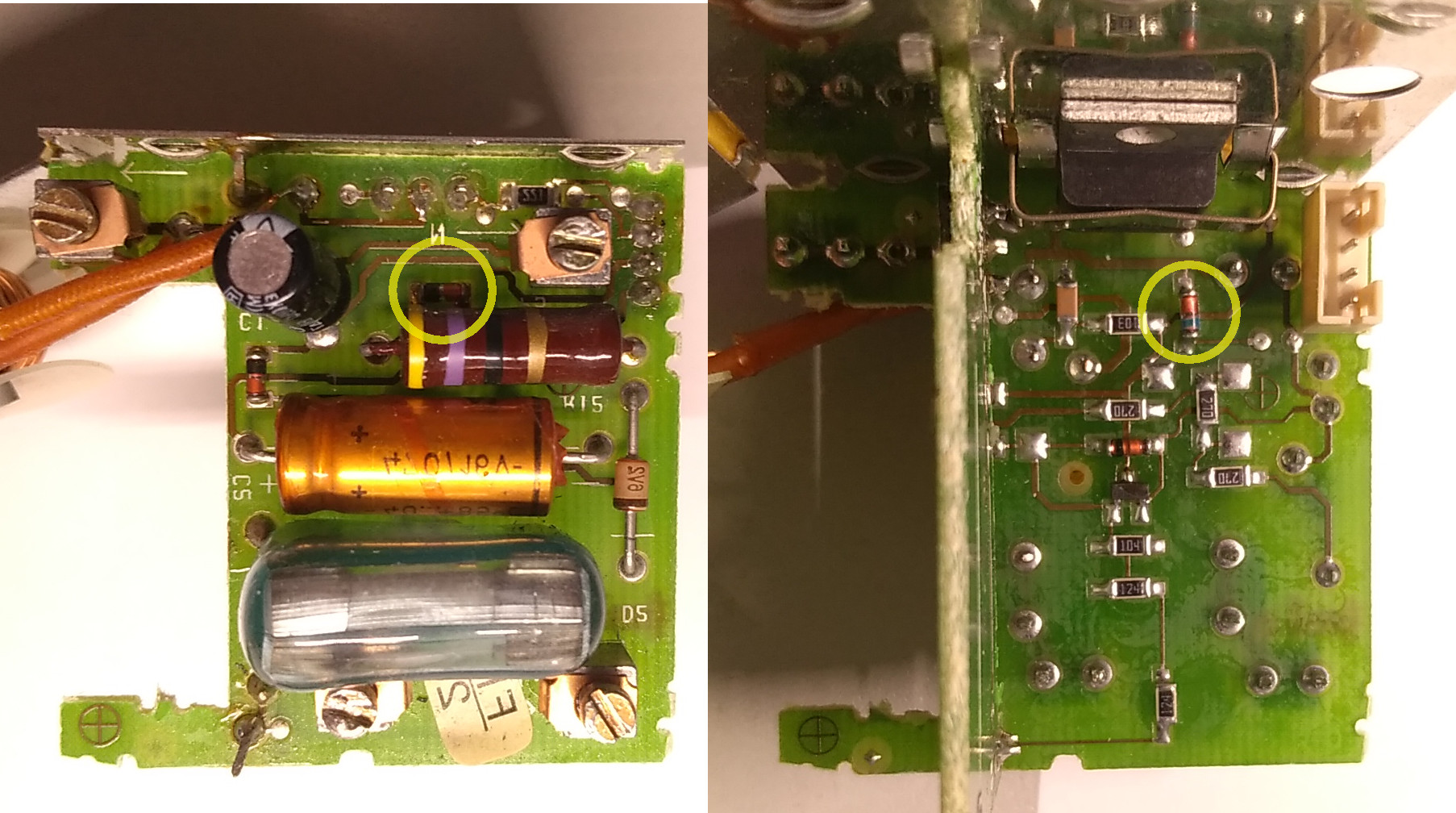
My LC1 was fixed with only the replacement of 2 diodes, circled on the following picture :
The 2 dead diodes are D1 and D2 on the schematic, and are part of the capacitor dropper circuit that provides provides the supply voltage. D1 died open, which means D2 saw a much higher voltage than it is rated for, and died short. I replaced both by LL4148 diodes, which fits this use case.
I also replaced the RIFA 22nF filter capacitor, as those are known to go bad spontaneously in a nice cloud of smoke
My LC1 is now working perfectly, and I can enjoy controlling a light from my B&O remotes.
Sadly today those devices are of limited use, as they can only control incandescent lamps.
I am tempted to design a replacement that could be used to control 12V LED lights instead.
Would any of you be interested in such a project ?
Location: France
My B&O Icons:
7 May 2022 at 14:30 #34055 SILVER Member
Thanks! And extra thanks for doing the schematic!
I’ll need to get the rest of my LC1s out and check those diodes! I had luck reviving at least three I think by just replacing the lithium battery.
Location: Helsinki - Finland
My B&O Icons:
26 May 2022 at 20:37 #34056HomersaurusBRONZE MemberExcellent work in providing the schematic.
I’ve had to repair an LC1 after it stopped working by replacing the BTA06-600T. Whilst it now functions, the maximum brightness is now limited so the schematic will be very useful in troubleshooting the problem.
-
AuthorPosts


- You must be logged in to reply to this topic.