
Home › Forums › General Discussion & Questions › ml powerbox alternative
- This topic has 31 replies, 3 voices, and was last updated 2 weeks ago by
 Madskp.
-
AuthorPosts
-
5 April 2024 at 04:17 #54108
Hello all,
Would you think a 5V USB to RJ45 cable could do the trick too?
A long time wish of mine is to get some sound im my garage. I already bought a BeoLab2000 for that reason. I like the idea that I can control source and volume without a remote or app. The only problem is that I cannot elegantly bring an ML cable to my garage. So my plan B is to use an Airport Express (as a wireless client), connected to a BLC, connected to the BL2000. Until I realized I need to power the ML network with an A. Master. I do have a spare 1611 that could do that, but I like the idea to use the BLC’s USB for that (and to keep the chain of boxes limited to two).
(OK I admit, that is a third box. And they are rare and/or expensive to various level of craziness!)
Reading the text, I was hoping that I could fabricate a cable that just brings the 5V USB of one socket to the correct RJ45 pins of the RJ45 ML socket of the BLC. Or am I seeing this way too simple? Has anyone done this?
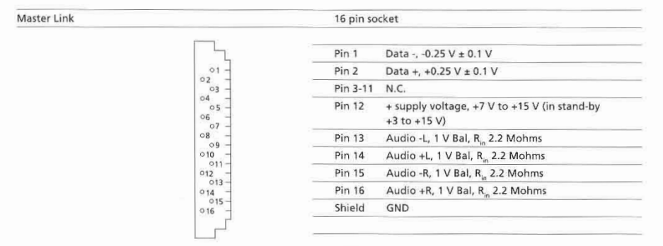
I am doubting myself, as the ML handbook says:
– supply voltage: -7 V to -15V, in standby -3V to -15V
+ supply voltage: +7 V to +15 V, in standby +3V to +15V
Hope someone else has been wondering about this also 🙂
Peter Pan is missed…
Regards, Johan
5 April 2024 at 05:11 #54109Hope someone else has been wondering about this also
I have been wondering about that powerbox indeed, and would very much like to know how much there is in it.
It migth be that it has to generate both the positive and the negative voltage to support the systems that need both.
However the Beolab 2000 among others only has connections for the positive voltage according to the specifications in the servicemanual for it:
And on the diagram
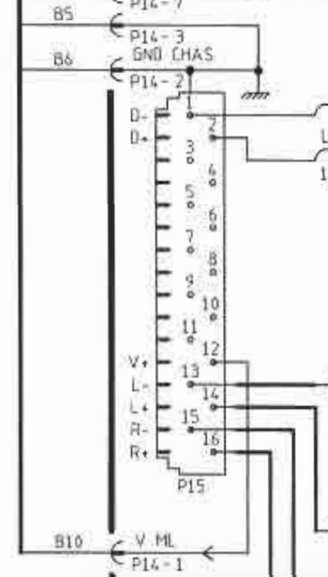
So it might be that by supplying the postive voltage to pin 12 is enough.
In some of my testing with the BL3500 this was not enough for stand alone operation, but in this case where you also has the ML data signals from the BLC it might be that could be enough.
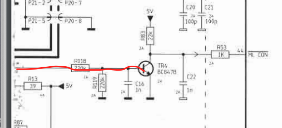
Looking at one of the other diagrams for the BL2000 I can see that the positive voltage fromt the ML connector is used to activate a transistor that activates a conenction called ML CON, which I assume is a way to tell the BL2000 that it is connected to ML.
I don’t know if it is this simple, but If you have some pieces of ML cables that are cut on the middle you could probably try to make an adapter.
I can also try some testing with a BL3500 but might not be before next week I have the time for it
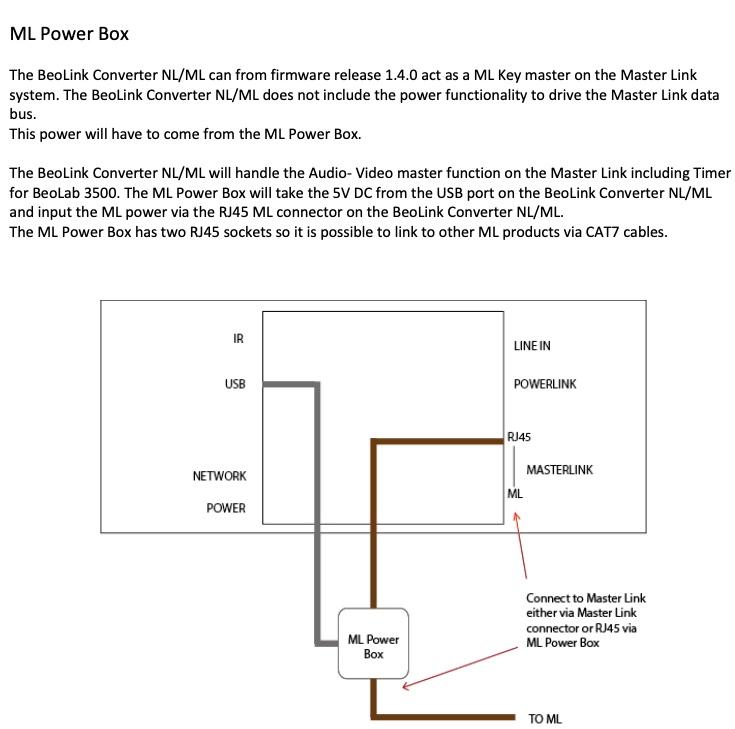
5 April 2024 at 05:30 #54110Just found this old thread about the ML Power box https://archivedforum2.beoworld.org/forums/p/16217/141383.aspx
There is especially on post that mention this:

Where the last part I have underlined with red might be a dealbreaker.
5 April 2024 at 05:59 #54111Hi Madskp, nice to have a fellow wonderer! When I will get my (5th) BLC I will produce a USB to RJ45 5V cable and test it. Trusting I will not brick the BLC with that! I read somewhere the thought that the BLC is mainly developed to bring ML sources to NL and not vice versa. This explains there was no need to provide ML power.
I also believe there is more going on inside the ML Power Box than just put 5v into ML. If someone has one, could open it and share a photograph of its magic content, that would help a lot I reckon. A mini flux capacitor could be in it? Who knows?
Regards, Johan
5 April 2024 at 06:21 #54112Hi Johan,
to be able to switch on and communicate with e.g. a BL2000 via ML following conditions must be met:
- DATA+ must be pulled up to around +0.25 V
- DATA- must be pulled down to around -0.25 V
- POWER+ must be at least powered with 5 V
In a standard ML system the master device will take care of that. I don’t know what the BLC misses out. Probably all of those conditions but you could measure that.
5 V is easy to apply. I recommend a series resistor and a diode for current limiting and reverse protection. The supply to the data lines is a bit more complicated and not easily achievable. If you have a negative supply you might get away with a few resistors and diodes.
I could probably build a few MDT boards with just the ML power circuit. That would more or less be a direct replacement for the power box.
5 April 2024 at 06:34 #54113Just to see what the BLC supplies I took mine out and connected it to power and a ML cable with loose ends.
On the the data + and – lines I can meassure 0.2-0.3V and – 0.2-0.3V so I would say that might be 0.25V (when taking my shaking hands into account 😉 )
On the pink vire I measure 10.8V and on the blue wire -10.8 V
So the BLC seems to have all the voltages coming out of it.
Now I am really confused what the ML power box does?
5 April 2024 at 06:54 #54114Hi B3OHACK3R, very nice to have you on board too! Could it be the BLC only fails to supply the POWER+? My ideal solution would be a ‘cable’ going from the USB socket to the MasterLink RJ45 socket of the BLC. I can then use the ML socket for the BL2000. Anything that comes close to that would be great!
Regards, Johan
5 April 2024 at 06:57 #54115Oh, okay. That is strange. I neither have a BLC nor a power box here currently. So can’t test. Maybe there are different revisions of the BLC?
From the electrical standpoint I can say for sure that it’s only the termination of the data lines as well as power on the Power+ pin that is needed.
5 April 2024 at 07:01 #54116Hi B3OHACK3R, very nice to have you on board too! Could it be the BLC only fails to supply the POWER+? My ideal solution would be a ‘cable’ going from the USB socket to the MasterLink RJ45 socket of the BLC. I can then use the ML socket for the BL2000. Anything that comes close to that would be great! Regards, Johan
🙂
As I said, the MDT board can easily used for that. Can be powered by USB and with a little modification then permanently provides power to ML. I could make one where only the ML power related parts are mounted.
I’m just a little confused by madskp’s measurements…
5 April 2024 at 07:13 #54117Could it be the BLC only fails to supply the POWER+
According to my measurements it does supply that.
What I noticed when I tried measuring again is that power + and – starts at a low voltage 3-5V when the BLC is booting, but then changes to the +10,8V and -10.8V when it is ready.
One thing I did not mention before is the blue/white wire for ML sense. That has no voltage, but should not be relevant to the BL2000. Also in the RJ45 ML cables it is connected to power+
If I can find the time in the weekend I will try to connect a BL3500 to see if I can make it do anything
5 April 2024 at 07:16 #54118When I have all components of my garage sound system I will also try it out and report!
Many thanks so far! J.
6 April 2024 at 10:02 #54119A little update from at testing session today.
I tried to connect the BLC to a BL3500 MK1 with a ML cable, and also connected the network link to my network.
On the BL3500 when I press Menu, 0, 2, GO it says No ML, so not registering it.
The voltages are also different when connected:
The pink Power + is now +4,68V
The Blue power – is now – 4,68V
Data + and Data – both are reading +0.4V which mean that at least the Data – can not pull the voltage to the correct level (-0.25V).
Also when I disconnect again and measure the data voltages they are both positive, and arround 0,3V. They might also both have been positive when I measured yesterday, so it could be that the missing negative data voltage is what the power box does?
6 April 2024 at 10:21 #54120I have now tried to a 1611 converter to the setup, so both the BLC NL/ML, BLC 1611 and BL3500.
Now the BL3500 says ML OK
The voltage on the Pink wire power + is 10.9V
The voltage on the blue vire power – is -10.9V
The voltage on the Green wire data + is 0.25V
The voltage on the green/white wire data – is -0.25V
So it seems that the BLC NL/ML does not have enough power to pull the voltages to the correct levels when a piece of ML equipment is connected.
So it might be that the options are:
- The ML power box
- A BLC 1611
- B3OHACK3R’s solution
- or a real ML audiomaster
6 April 2024 at 11:27 #54121Hi Madskp, thanks for that! I will see to find an ML power box and share photographs of its content, just out of curiosity! Regards, Johan
6 April 2024 at 12:26 #54122Hi Madskp, thanks for that! I will see to find an ML power box and share photographs of its content, just out of curiosity! Regards, Johan
It could be very interesting to see whats inside it
12 April 2024 at 03:11 #54123No flux capacitor! It does have an LED though.
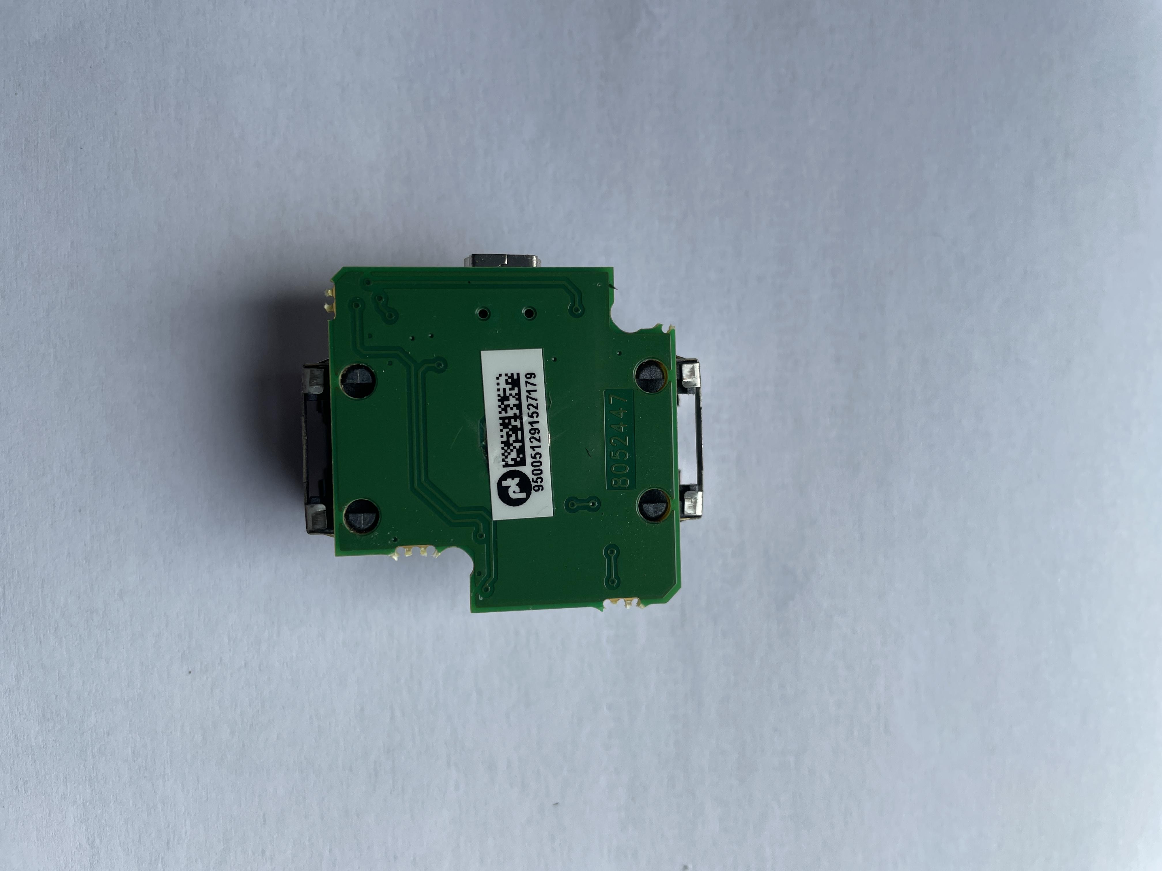
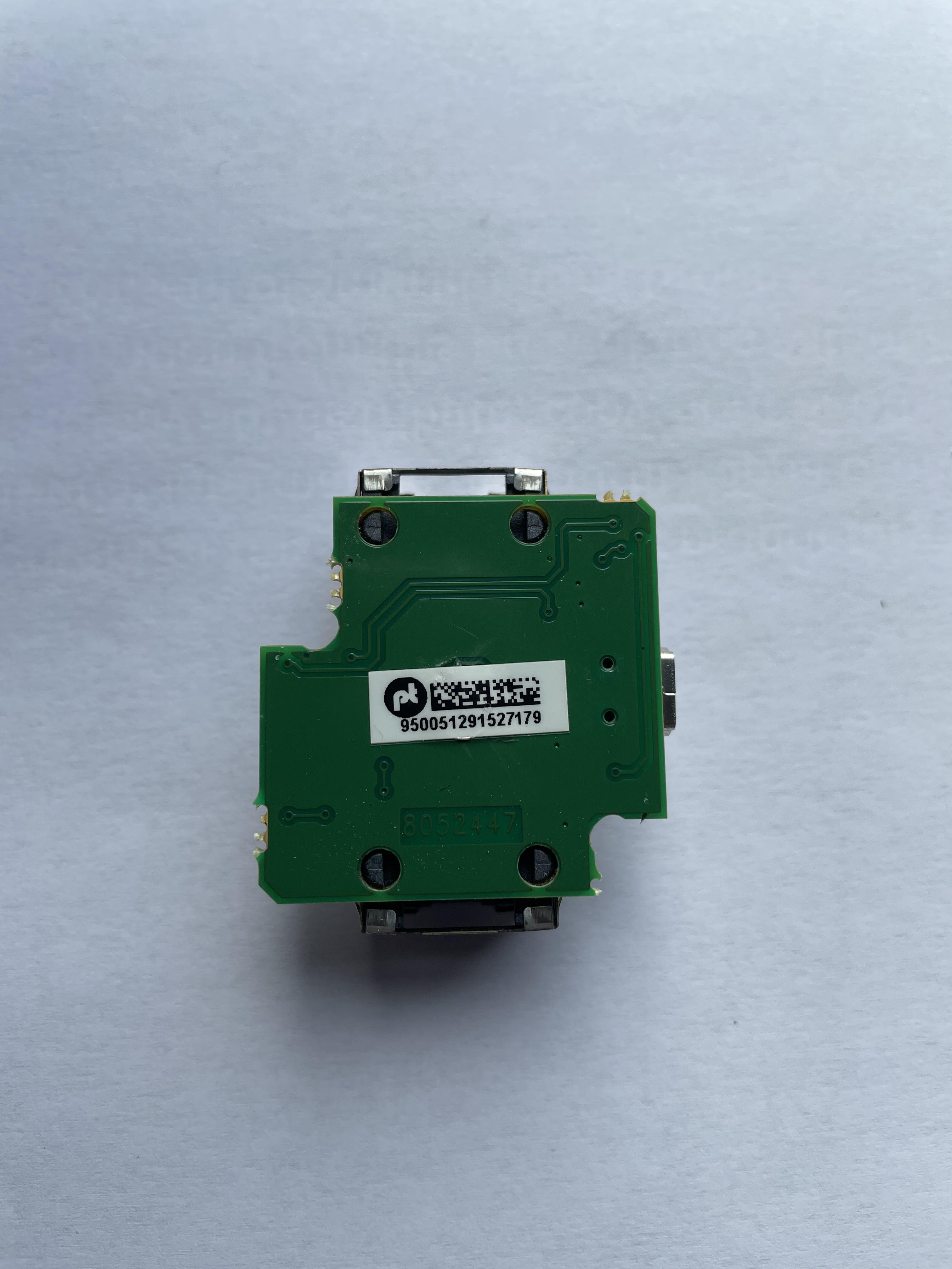
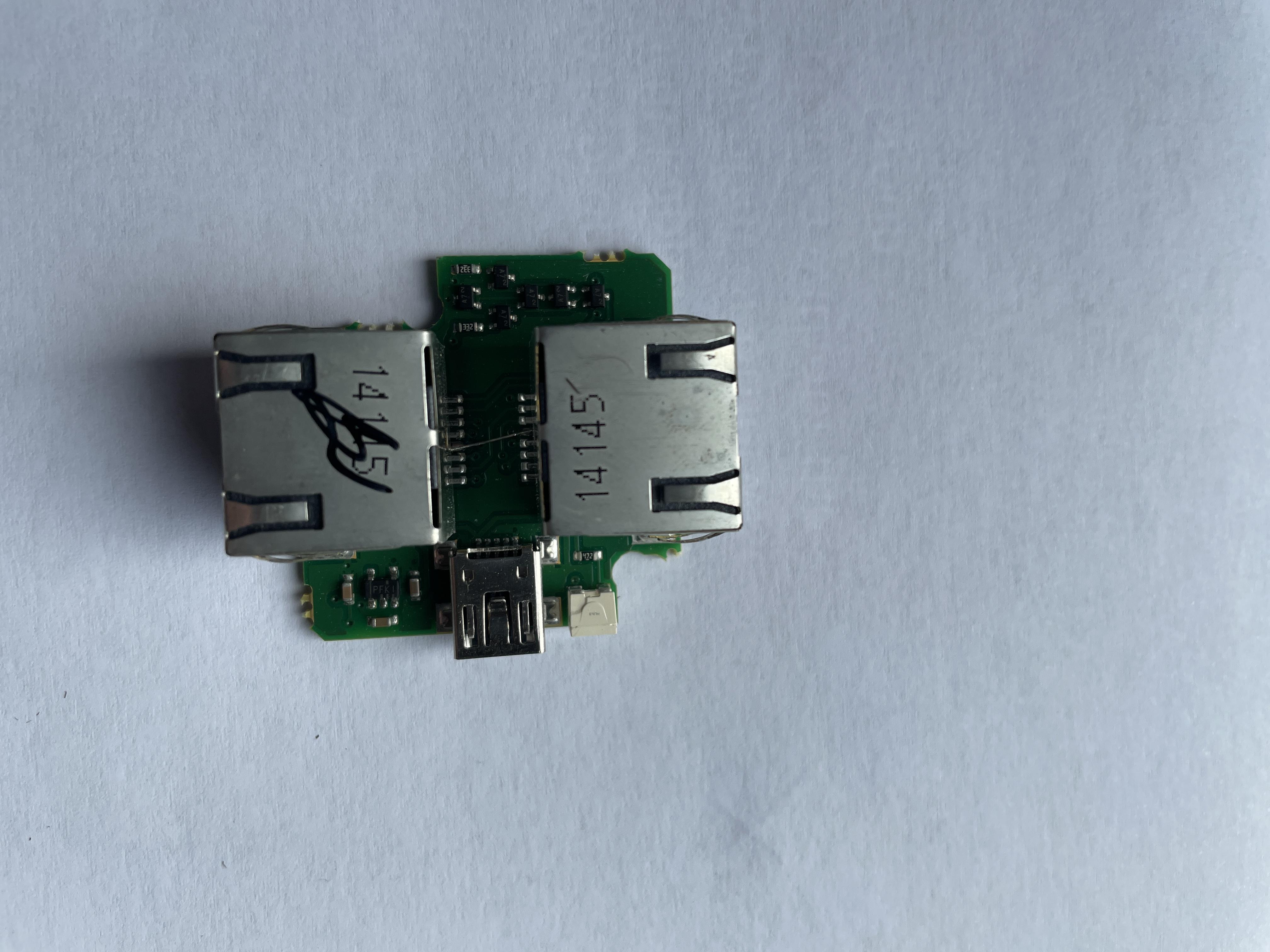
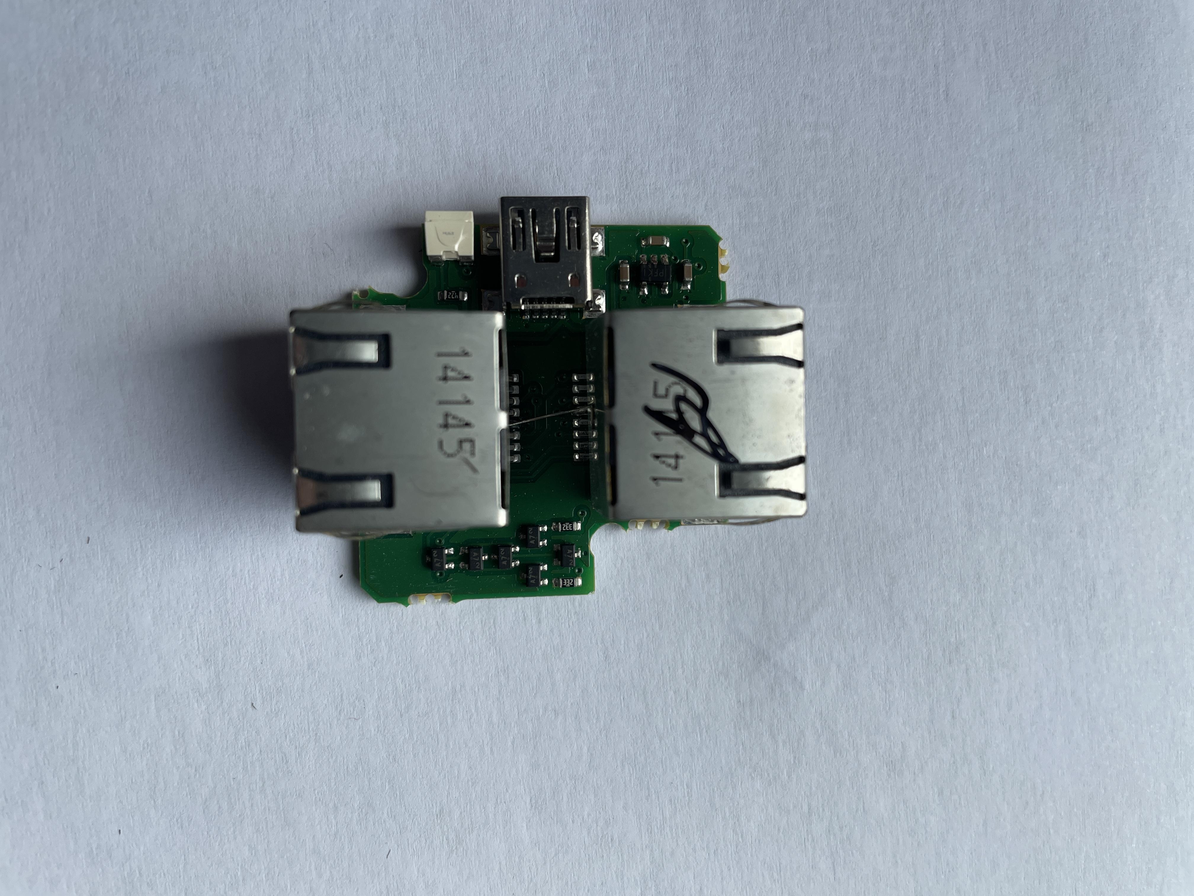
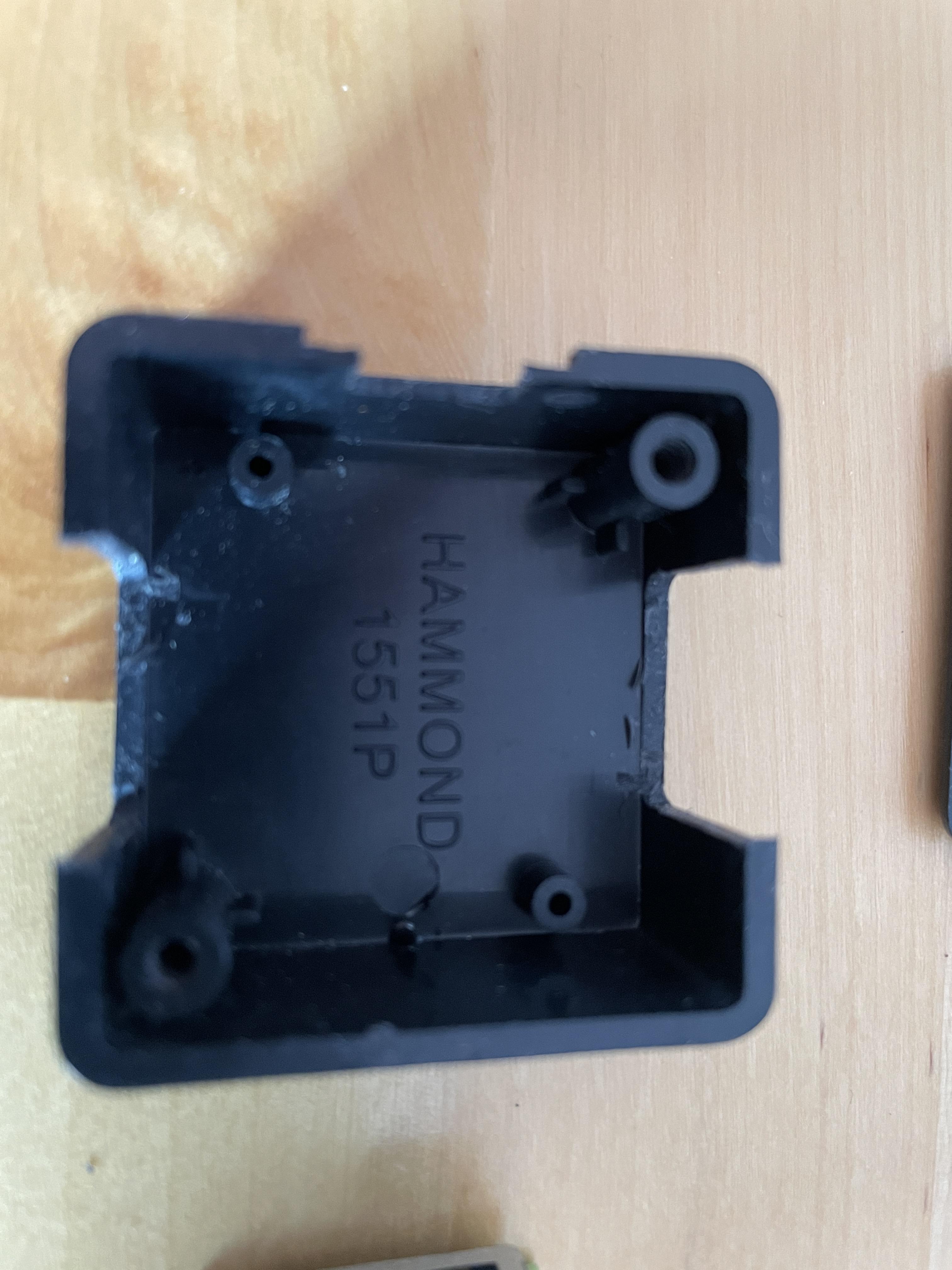
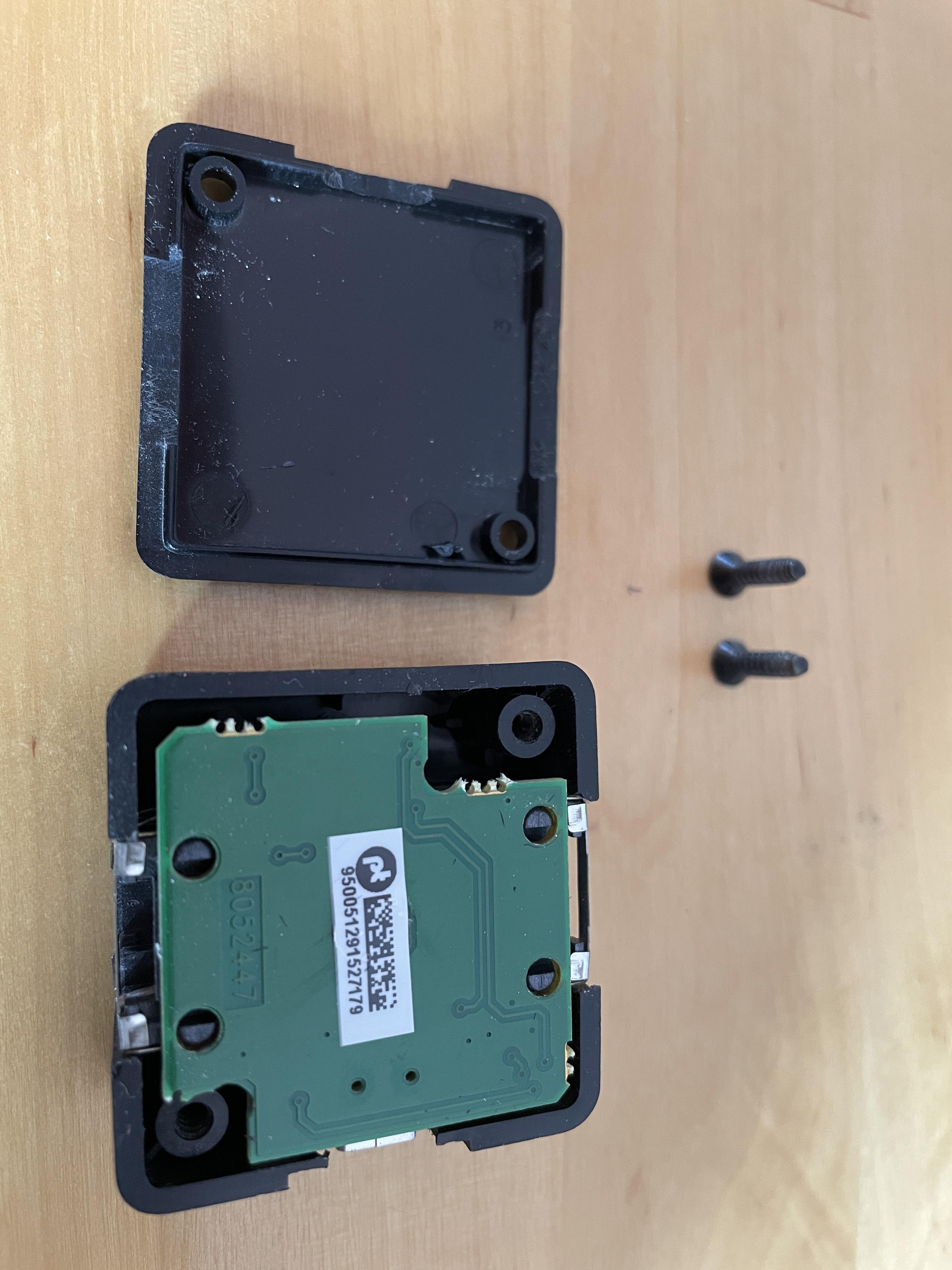
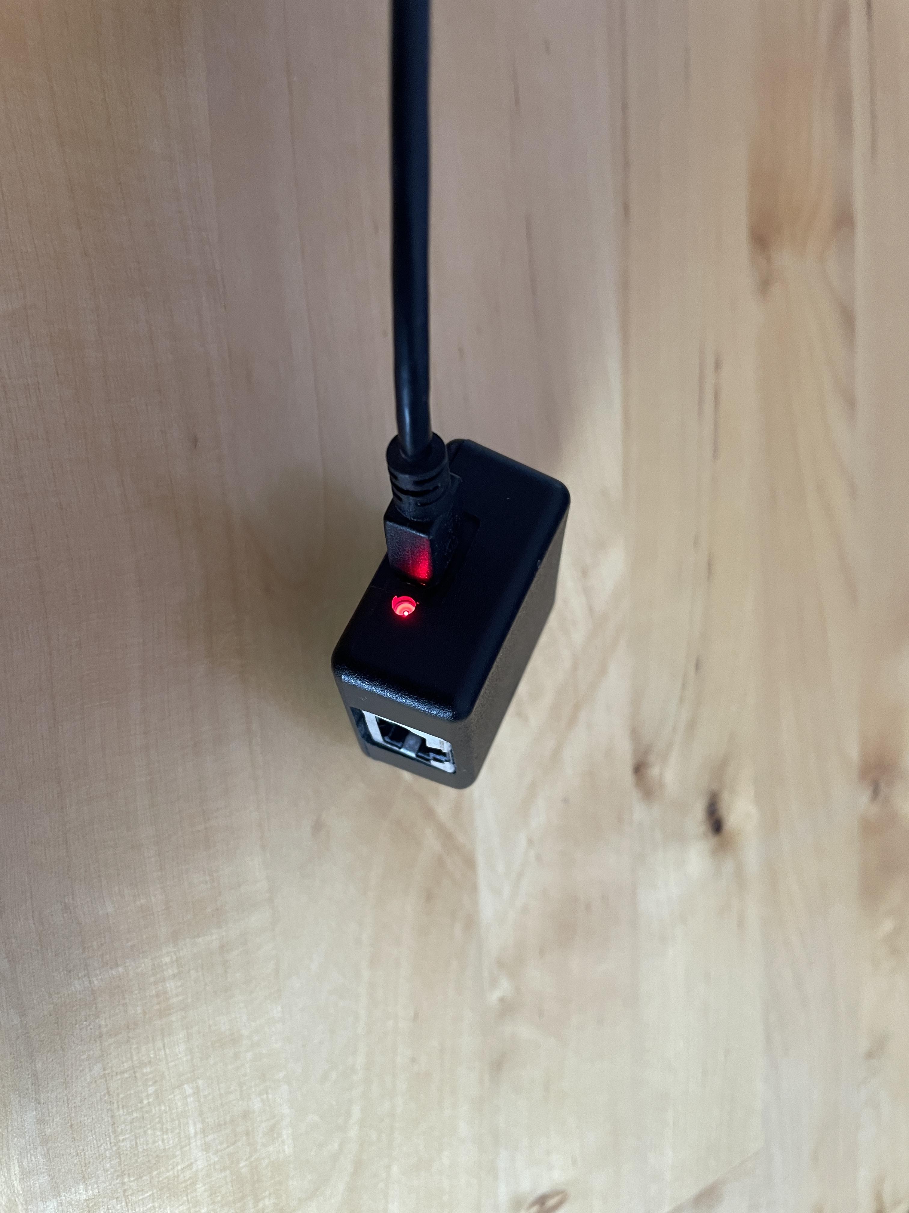
 I really cannot tell what the (tiny!) electronics do. If I did not capture a detail that is of use, let me know, and I can try to make a close-up with a camera.12 April 2024 at 03:45 #54124
No flux capacitor! It does have an LED though
I really cannot tell what the (tiny!) electronics do. If I did not capture a detail that is of use, let me know, and I can try to make a close-up with a camera.Thanks for the look inside. At least it’s not just an empty box with some wirering from USB to RJ45 😉 but I can be discussed if the components inside reflects the price these boxes are sold at used.
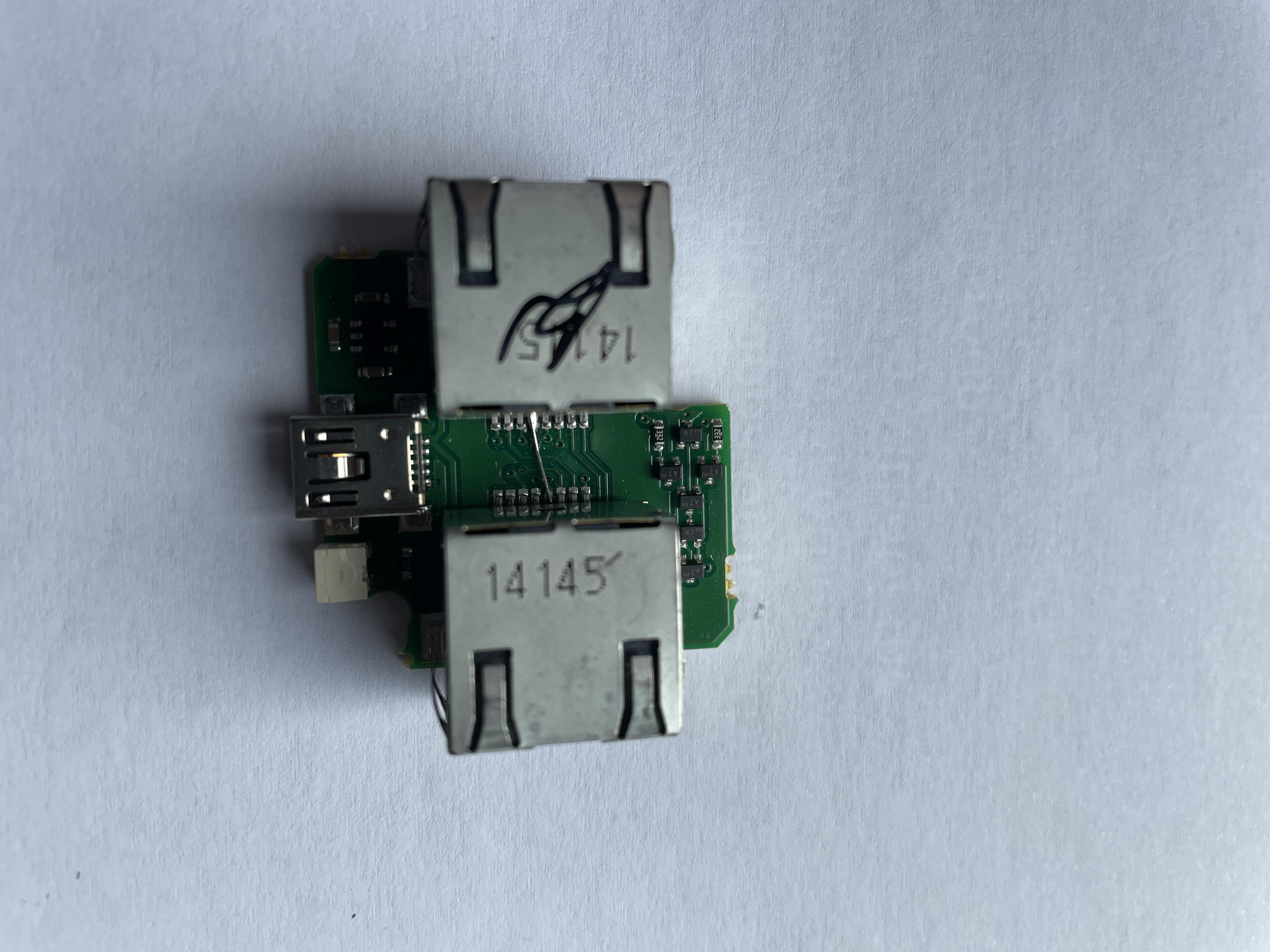
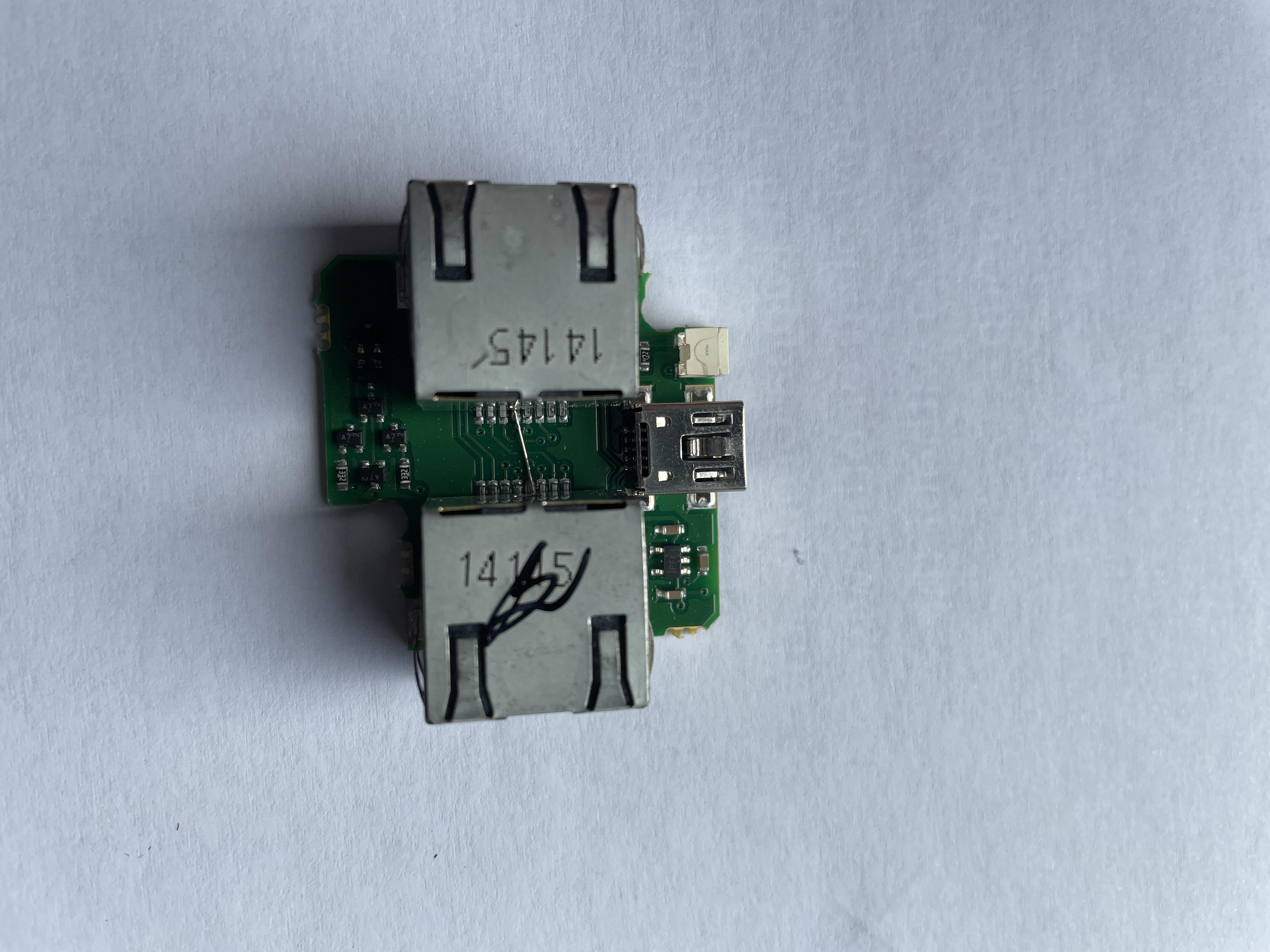
I tried to google the 5 pin IC and it looks like it’s some kind of power regulator
https://www.indiamart.com/proddetail/pfki-24844731397.html
The small 3 legged transistor looking components seems to be some kind of diode
https://www.indiamart.com/proddetail/a7-smd-diode-19562740788.html
13 April 2024 at 01:47 #54134Thanks Madskp – ML Power box still part of the factory planning :-). Regards, J.
13 April 2024 at 09:00 #54125Madskp, B3OHACK3R, would you believe that a BeoLink Passive provides the required MasterLink voltage (as the 1611 does)? I do have one of those lying around. With two CXs and an IR eye (and a remote) I could maybe also keep the number of sound factory boxes limited to two. Regards, Johan
13 April 2024 at 09:16 #54126Interesting. Roughly what I expected to be in there.
The 5-pin chip is an unregulated charge pump used for inverting the + 5V from USB to -5V.
The smaller ones on the other side of the board are indeed some diodes and two resistors. They are used for providing power to the data lines.would you believe that a BeoLink Passive provides the required MasterLink voltage (as the 1611 does)?
No, unfortunately it can’t.
-
AuthorPosts
- You must be logged in to reply to this topic.