


Home › Forums › Product Discussion & Questions › BeoMaster › Is the TC9177P IC4 a common failure on the Beomaster 6500 pre-amp?
- This topic has 12 replies, 5 voices, and was last updated 3 years, 1 month ago by
 quattttro.
-
AuthorPosts
-
18 May 2023 at 04:41 #46722
 quattttroBRONZE Member
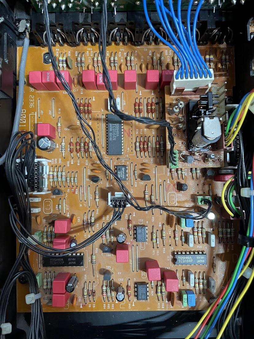
I’ve got no sound from the left channel and irregular volume levels on the right from the pre-amp. I’ve traced the signal to the inputs of IC4 (Toshiba TC9177P), but nothing on the left channel output of that chip. The +/- 12V supply to that chip is fine.
 18 May 2023 at 19:42 #46723DillenModerator
All components can fail.
Is the TC9177P IC a typical problem and a well-known trouble maker IC?
– No.Have I seen TC9177P ICs fail?
– Yes, once or twice in thirty+ years.Considering the amount of work done to the module you show, I’d say check the work that was done as that alone could have caused the problem.
Oh, – and don’t forget to replace that speaker relay. Cleaning its contacts will only provide a temporary solution, and leaving it open like that won’t help it in any way.
Martin
19 May 2023 at 01:28 #46724quattttroBRONZE MemberThanks for the reply, I will do some further testing if a replacement chip doesn’t solve the issue.
The relay cover is only off for testing. I checked there first for for the fault.
19 June 2023 at 17:44 #46725quattttroBRONZE MemberI’ve replaced TC9177P, but the problem of no sound on the left channel remains. I get a perfect sine wave at the inputs for this chip (pin 5 & 16), but nothing on the first outputs for the left channel (pin 17 &4). The +/- 12V supply to the chip is right on and steady.
The only thing I can think of is the balance control is set to the max right channel, and this is saved despite disconnecting the 3V microprocessor board battery. I don’t have a proper remote for this unit, yet, but does this sound likely or possible?
 20 June 2023 at 13:54 #46726GlitchBRONZE Member
Do you have a logic analyzer (or oscilloscope) to check the DATA/CK/STROBE signals? Manually decoding the DATA packet will answer your “balance” question.
Are the chip grounds solid?
Glitch
20 June 2023 at 14:45 #46727Die_BogenerBRONZE MemberBalance max to the right and no sound on left?
Quite normal. Everything ok.
Just center the balance.
Working without the lithium cell is a very bad idea.
20 June 2023 at 15:49 #46728If the backup battery has been replaced I always perform a erasure of the memory. That set back the basic settings. After that you mostly have to set the FM display offset. But that’s easy.
Location: Utrecht
21 June 2023 at 01:36 #46729quattttroBRONZE MemberGlitch, I do have an oscilloscope, will try to probe the signals, not sure what to look for though. Tested all of the grounds, all good. At this point, it might be best if i find a proper remote
If the backup battery has been replaced I always perform a erasure of the memory. That set back the basic settings. After that you mostly have to set the FM display offset. But that’s easy.
Beobuddy, I believe you need a remote to perform this reset.
21 June 2023 at 09:05 #46730For erasing the memory you can use a Beo4, BL1000 or MCP.
For setting de FM display setting you’ll need a MCP. Only then you’ll get the frequency displayed. But then again, if you’re just a bit off the correct frequency while tuning with a Beo4 for instance, who will notice 😉
I have several MCP’s and Beo4’s laying around, so never thought of that issue. But with a Beo4 you can check and store the sound settings.Location: Utrecht
21 June 2023 at 13:08 #46731GlitchBRONZE MemberGlitch, I do have an oscilloscope, will try to probe the signals, not sure what to look for though. Tested all of the grounds, all good. At this point, it might be best if i find a proper remote
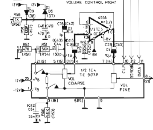
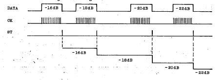
Checking the DATA should be pretty straightforward (if you want to poke around while waiting for your remote to arrive). The diagrams below are from the cTC9177P datasheet.

Connect the scope to DATA, CK, and STROBE signals and “single trigger” the scope off the STROBE.

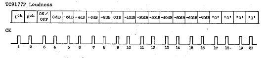
Once you have a data packet captured it can be decoded with the info above. There is also a more detailed description in the datasheet. It looks like two DATA packets will need to be captured, one for the L command and one for the R command, to debug possible balance issues.
Glitch
21 June 2023 at 15:21 #46732quattttroBRONZE MemberThanks for the info, I just managed to resolve it though with an old Harmony remote. The balance was indeed set to full right channel. Everything working now.
21 June 2023 at 15:50 #46733GlitchBRONZE MemberThat is good to hear.
Just curious, what was the cause for the “irregular volume levels on the right” channel that you mentioned in the original post?
Glitch
22 June 2023 at 02:08 #46734quattttroBRONZE MemberIf you look at the first post, you will see C54 is missing. I believe that was why it was behaving strangely. I forgot that one!
-
AuthorPosts
- You must be logged in to reply to this topic.