
Home › Forums › Product Discussion & Questions › BeoGram › Beogram 4004 (Type 5526) Issues
- This topic has 9 replies, 3 voices, and was last updated 1 year, 5 months ago by
 Mark-sf.
-
AuthorPosts
-
16 October 2022 at 03:49 #10811
I have a Beogram 4004 (Type 5526). When pressing and holding “START” the carriage will immediately start (seems very fast) and move clear to the end of the slide transport and keep moving until it comes off the spindle. If I remove my finger from “START” it the Beogram immediately stops. The speed is almost like the speed of the fast tracking, when the turntable is operating normally.
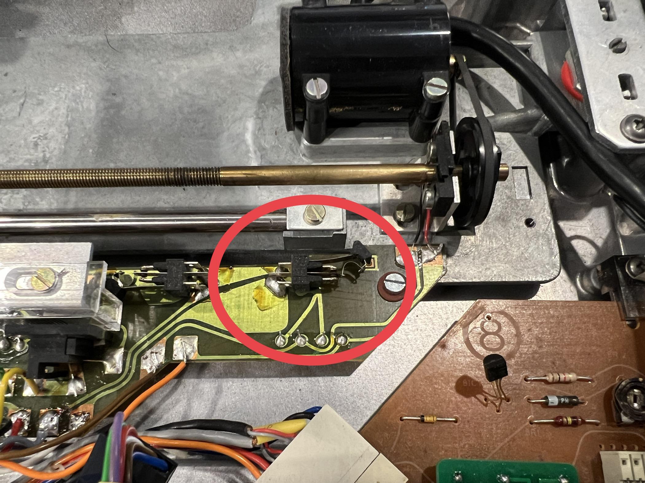
When pressing the “33” button, with the carriage in the home position, the slide transport starts moving toward the center and almost immediately stops after pressing “33”. The point at which it stops is when the switch (circled in red) is released into the open position. I am truly at a loss, obviously something is grounding out. Is there anyone that can help me work through these issues? I have replaced all the capacitors (and checked for correct polarity), and replaced both RPM switching relays.
 17 October 2022 at 00:54 #26327
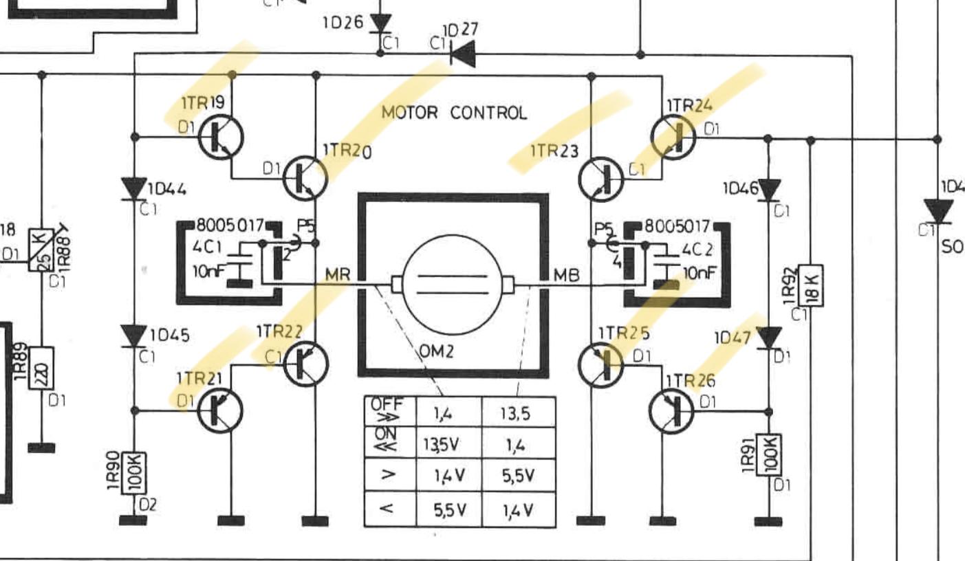
I am having trouble parsing the symptoms you are reporting. In normal operation, simply pressing start momentarily will cause the tonearm to move to the edge of the record and lower. If you press and hold then it will continue past that point until you release. Pressing 33 should just cause the turntable to spin for cleaning without the arm moving. If it is then you may have a shorted transistor in the servo motor control section. You can see a table of voltages on the schematic available at https://beomanuals.com/manuals/Beogram/Beogram%204004/Bang-Olufsen-Beogram_4002-4004-Schematic-2.pdf.
17 October 2022 at 18:23 #26299Hi Mark,
Is this the relevant section of the schematic with all the associated transistors?
 17 October 2022 at 23:52 #26295
Yes it is.
18 October 2022 at 00:02 #26292I took your advice and started checking all the voltages and connections – once confirming that all of the white jumpers were correctly wired, I then decided to test all of the black transistors. TR-6, TR-17, and TR-19 (which given the schematic, seemed to cause the servo motor issue) were each out of spec and were replaced with new BC 547B transistors.
Now the issue of the 33 RPM button engaging the slide transport, is gone. I can press the 33 RPM button and the unit will not engage the slide transport without me pressing “<“. That said, when pressing the “<“ after pressing the 33 RPM button, the slide transport starts, but then dies. Some progress, although minute!
The “START button will only work by pressing and holding it down. The slide transport (now) seems to be the correct speed and not fast as before. Once “START” is let go, the slide transport stops and the solenoid engages and disengages. Allowing the slide transport to go clear to the end results in it wanting to return, but with the issue of the slide transport stopping and the solenoid engaging and disengaging (all while holding “START”). I have uploaded a new video here of an explanation and the phenomena.
18 October 2022 at 15:39 #26280What are all those white wires on the main PCB?
And where does that module with the SMD caps come from?
From the trademark logo I assume it must be a genuine Bang & Olufsen board, but I don’t recognize it.Martin
18 October 2022 at 22:28 #26263Hi Martin,
The white wires are being used as jumpers. The previous owner had no electronics and soldering experience. When replacing capacitors, he ripped up PCB wire hole tracks 🙃.
The board with the Bang & Olufsen logo is a replacement 4000 uF power board, to replace the original obsolete unit. It’s just for my personal use and I was playing around with PCB silkscreening.
Ian
19 October 2022 at 04:18 #26261Thanks for the video. Some of what you are observing is normal. For example, the 33 button record clean function ONLY works when the arm has not left its home position. Also, the single arrow buttons do NOT work until the tonearm has left the home position. Finally, the >> and << and >> do not need to be held down.
The two major problems I see are the following:
- The return servo motor direction is not functional as it should not only engage when you press and hold > or press >> but also when it gets to the center endpoint.
- Your solenoid is engaging but not holding as it’s there to keep the tonearm lowered. This means that there is an insufficient voltage on the coil when it switches to its “hold” mode.
These are likely independent, and you have multiple issues. Go back to the servo motor circuit for #1 and the Solenoid circuit made up of TR9,10 and IC4 and its caps.
3 November 2022 at 04:41 #25789Hi Mark,
I am currently in the process of replacing all associated components in both the servo motor control and solenoid circuits. Upon inspecting TR-22, (the BC143 transistor)I found that it does not test properly and I compared it with the one on my other 4004 board that functions properly. I suspect that this transistor has failed and I ordered a NOS replacement from Littlediode in the UK. It should arrive in the next few weeks. I will report back the findings and hopefully this solves the issues with this board. Thanks!
Ian
4 November 2022 at 03:39 #25762Hi Mark,
I was able to find another BC143 transistor! I installed it and the Beogram works, but the “<” button does not work. For some reason, I cannot seem to find what part of the circuit is responsible for the “<” button. Any ideas?
Thanks again!
Ian
-
AuthorPosts
- You must be logged in to reply to this topic.